Summary of PBUS – an RS485-like multi-drop bus with half duplex serial protocol
This article describes three PIC source versions (PB12, PBUS, PB628) for a PBUS protocol, a one-master, multiple-slaves half-duplex serial communication bus running at 2400 baud. Devices connect via two wires (GND and PBUS) and have unique IDs. Packets are up to 18 bytes with a checksum. Timing ensures synchronization with specific gaps and response windows. Commands allow version checks, pings, and statistics. Communication handles errors and device identification efficiently. Hardware details emphasize open-drain output and diode use for safe bus driving. The PBUS protocol enables simple multi-drop networking for PIC devices.
Parts used in the PBUS project:
- PIC microcontrollers (e.g., PIC16F84, PIC16F628)
- Open-drain output pin (RA4 on PIC16F84)
- Hardware UART pins (RB1/RX, RB2/TX on PIC16F628)
- Diode for TX pin protection
- Two-wire bus connection (GND and PBUS signal line)
overview
There are three PIC source versions:
- PB12 is for 12-bit slave devices without interrupt
- PBUS is for slave devices with an interrupt, software UART implementation
- PB628 is for slave devices with an intterupt and a free hardware UART
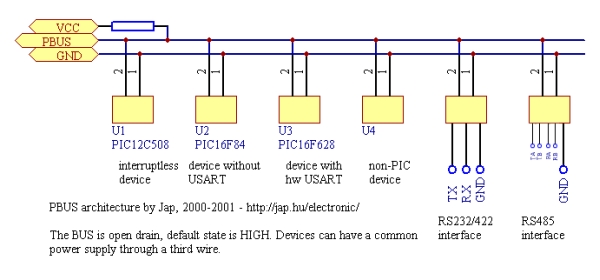
PBUS assigns a unique device ID in the range 1-f for every controller on the bus. The maximum number of slave devices on one bus is maximized in 15. Current protocol is one master, multiple slaves.
The implementation uses 2400 baud half-duplex serial communication. Only 2 wires (GND and PBUS signal) are needed to interconnect devices using their own power supply. Using a higher speed or other protocols on the same PBUS is possible, since slaves won’t respond to packets they can’t interpret.
 packet structure
Packets consist of 8-bit bytes. All packets contain at least 3 bytes. Maximum length is 18 bytes.
| byte offset | bits | name | description |
| 0 | 7-4 | DEVID | destination device PBUS ID |
| 0 | 3-0 | LEN | optional data length (0 means packet is 3 bytes, no optional data) |
| 1 | 7-0 | CMD | MASTER command or SLAVE response code |
| 2 | 7-0 | DATA[] | optional data, length is given in LEN (LEN=0 means no data) |
| 2+LEN | 7-0 | CHKSUM | packet checksum. Added to the packet bytes sum will result a sum of zero |
PBUS timings
Master devices generates a 8500 usec gap on the bus before transmitting a PBUS packet. This is for synchronization of all listening receivers. Receivers can expect to see a min. 4900 usec, max. 21200 usec gap. Packet bytes must be sent without interruption. Packet reception will be reset if a gap longer than 200 usec is detected. After the request packet is sent, the master waits up to 1000 usec for a reply from the addressed slave. Slaves check received packets in this order:
- check for a valid checksum. If invalid, drop packet and go back listening
- check for own device ID. Ignore all other IDs without response
- if the command is not implemented, ignore the packet and go back listening
- process the command and generate a response with a destination device ID 0
PBUS commands
PBUS handlers will implement some commands internally.
Commands implemented by ALL sources:
| dev | cmd code | cmd parameters | description |
| M | 5e | CVER | (check node version) |
| S | 60 | ROK <pbus version> [main version] [optional string describing node] | current nodes do not return the optional string by default |
| M | 5f | CPING [optional data] | (test if a node is present and the link is up) |
| S | 6f | RECHO [optional data echoed] | PB12 sources will not echo the supplied ping data back |
 Commands implemented by sources except PB12:
| dev | cmd code | cmd parameters | description |
| M | 58 | CNOOP | (no operation) |
| S | 60 | ROK | |
| M | 5b | CLAST | (repeat last response) |
| S | (copy of the last response packet sent) | ||
| M | 5c | CRES | (reset statistics counters) |
| S | 60 | ROK | |
| M | 5d | CSTAT | (get PBUS statistics) |
| S | 60 | ROK <e1> <e2> <e3> [optional counters] | The CRES and CSTAT commands can be disabled. |
Meaning of counters:
| name | description |
| e1 | number of checksum errors |
| e2 | number of good packets received |
| e3 | number of good packets sent for me (not necessarily answered) |
Hardware interfaces for PIC devices
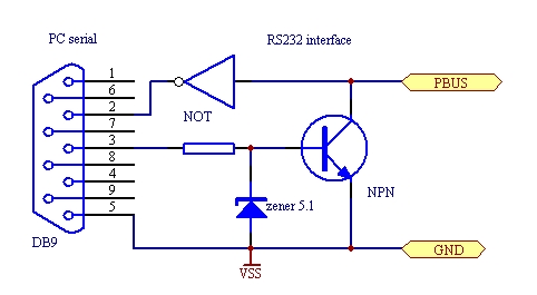
The most simple case is when the controllers are close and you can directly wire them. If you use another pin than RA4 (open drain output) on the sw-UART 16×84 or use a hardware UART chip (eg 16F628), you need the diode on the TX pin as shown on the schematic, because devices can only drive the bus LOW, never HIGH. If you choose a hardware UART version, use the appropriate pins (RB1/RX, RB2/TX on 16F628).
For more detail: PBUS – an RS485-like multi-drop bus with half duplex serial protocol Schematic

