USB interfacing for AVR microcontrollers
Since the release of V-USB, dozens of projects have been made that allow an AVR to communicate over USB. USB data signals are supposed to be in the range of 2.8 to 3.6V, so there are two recommended ways to have an AVR output the correct voltage. One is to supply the AVR with 3.3V power, and the other is to use 5V power but clip the USB data signal using zener diodes. Most implementations of V-USB, like USBasp, use the zener diodes. I’ll explain why using a 3.3V supply should be the preferred method.
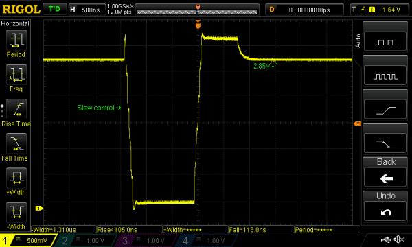
Pictured above is a capture of D- line on a chinese USBasp, showing one of the 1kHz SE0 idle pulses. The idle voltage is close to the 2.8V limit because this particular USBasp uses a 2.2K pullup resistor to +5V. Using a 1.5K pullup as is recommended on the V-USB site puts it closer to 3.2V, which is the high voltage level from the host.
To determine how the signal is read by the AVR, we can look at the ATmega8A input threshold graphs at section 28.8 of the datasheet.
For more detail: USB interfacing for AVR microcontrollers