
Summary of Making a 8×40 LED matrix marquee using shift registers
This project details the construction of a mono-color 8x40 LED matrix display using a PIC16F1847 microcontroller. The system accepts text input via USB-UART from a PC, storing messages in EEPROM to scroll across 320 LEDs arranged in five cascaded 8x8 modules. Row scanning is managed by ULN2803 drivers, while column data is shifted through five 74HC595 registers. The firmware utilizes mikroC Pro and communicates at 115200 bps, allowing users to update displayed content dynamically.
Parts used in the 8×40 LED Matrix Display:
- PIC16F1847 Microcontroller
- Five 74HC595 Shift Registers
- ULN2803 Darlington Array IC
- Five NFM-12883AS 8×8 LED Modules
- LM7805 Voltage Regulator
- VECTOR ELECTRONICS 3-hole solder pad perfboard (4.5″ x 8.08″)
- USB-UART Interface Module
Theory
If you are not familiar with LED matrices at all, I strongly suggest to read my two experimental tutorials that were posted earlier: Basics of LED matrix display and Scrolling text message on an LED matrix. The first tutorial describes the basic structure of LED matrices and the multiplexing technique of driving them to display static characters. The second tutorial is focussed more on creating animation and demonstrates the concept of displaying a scrolling message on a matrix of 16×8 LEDs. This project is basically a continuation of those two tutorials and I am hopeful it will further improve your understanding of driving a bigger size LED matrix display, both at hardware and software level. The operational part of the project hardware is described in the following section along with the circuit diagram.
Circuit diagrams
Five 8×8 square LED display modules are arranged in a linear fashion to construct an 8-row X 40-column display matrix. The LED display modules I used in this project are NFM-12883AS from Futurlec. They are common-row-cathode type, which means the cathodes of all the LEDs in each individual row are interconnected, and therefore each row pin is supposed to sink currents from eight LEDs in that row. The similar row pins of all 5 modules are further connected together and are fed to the the output sinks of an ULN2803 IC, which consists of 8 Darlington arrays. Now each output pin of ULN2803 is a sink for 40 (=8×5) LEDs in that particular row. Since ULN2803 can sink current up to 500 mA per pin, the current per LED is limited to 500/40 = 12.5 mA.
The anode terminals of LEDs are accessible through column pins. Since we are going to apply row scanning technique (read Scrolling text message on an LED matrix), each column pin needs to source current for only one LED, as only one row is active in that column at a time. The columns are driven by the outputs of a 40-bit serial-in-parallel-out arrangement constructed by cascading five 74HC595 ICs. The 74HC595 device is an 8-bit serial-input and parallel/serial output shift register. The serial output feature allows cascading of multiple 74HC595 devices. From engineering point of view, 74HC595 may not be a good choice as column drivers because they are not meant for sourcing current for LEDs. But several experiments done by people (including me) have shown that they can drive LEDs reasonably bright, and therefore can be used as column drivers in an LED matrix project like this.
The microcontroller used in this project is PIC16F1847 from the enhanced mid-range 8-bit PIC family. It runs at 32 MHz using its internal clock source (with PLL enabled). PORTB provides ground path for individual rows (cathode) through the ULN2803 darlington pair array, whereas RA0, RA1, and RA2 pins are used to control the Data, SH_CP, and ST_CP lines of the cascaded shift registers. Pin 8 and 7 of PIC16F1847 are the default pins for UART communication. They go to the USB-UART module for serial communication with the PC. A serial terminal program running on the PC can be used to send character data to the microcontroller which saves the received information into its internal EEPROM.
I constructed the above circuit on a general purpose perforated prototyping board. You definitely need a bigger one to fit all 5 LED display modules along with other components. I used VECTOR ELECTRONICS 3-hole solder pad circuit board from Newark which is a very good quality 4.5″ x 8.08″ perfboard. An LM7805 IC is used to derive regulated +5V power supply. The power supply circuit is not shown above because it is a very common circuit and I assumed you know it.
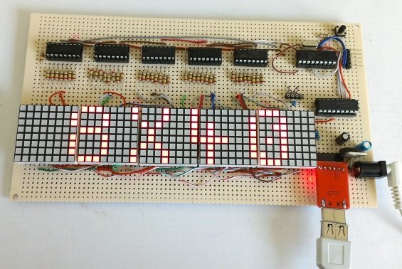
The following picture shows the finished LED display board with an USB-UART module plugged in. [A crystal oscillator is also seen in the board but it is not really used. The microcontroller runs at 32MHz using its internal clock source. I first thought I would use an external clock, but later changed my mind but I was lazy to take the crystal off the board.]
Software
The firmware for this project is developed using mikroC Pro for PIC compiler. The program uses an 8×5 byte (=320 bits) array (Buffer[8][5]) to store the display pixel information. Each bit corresponds to one LED. The user can send message from PC to the display board using a serial terminal program. I am using Termite 2.9 program on Windows. The message sent is saved onto the PIC’s internal EEPROM. The first two EEPROM locations are reserved for a data input flag and number of characters in the message. The following sequence describes in detail how the firmware of this project works.
- Power is turned ON. The PIC MCU initializes the ports, and listen to its serial port. It prints a message ‘ARE YOU READY FOR YOUR INPUT? Y/N’ to serial port and the message is displayed on PC serial terminal application window. The user gets 3 seconds to send character ‘Y’. Otherwise, the MCU continues and displays the pre-stored message. The message is displayed scrolling from right towards left. The serial communication between the MCU and PC happens at 115200 bps.
- If the user sends ‘Y’, the MCU waits for incoming data. The MCU reads the incoming bytes until it receives ‘#’, which is an indicator of last character byte sent from the PC. The MCU then writes 1 to EEPROM location 0×00, and saves the number of bytes received at EEPROM location 0×01. The received characters are sequentially saved into sequential EEPROM locations starting from 0×02.
- Next, the MCU loads the character data from EEPROM into RAM and display it on the LED matrix scrolling from right to left. Each character is mapped to its graphic font which is saved in to the program memory as static array. Please read Scrolling text message on an LED matrix tutorial for more detail on LED matrix font.
For more detail: Making a 8×40 LED matrix marquee using shift registers
- How many LEDs are used in this project?
The project uses 320 LEDs arranged in 8 rows and 40 columns. - What microcontroller drives the display?
The PIC16F1847 microcontroller is used as the heart of the project. - Can the 74HC595 ICs source current for LEDs?
While not designed for sourcing, experiments show they can drive LEDs reasonably bright for this application. - How does the system receive data from the PC?
Data is received via a serial port or USB-UART interface running at 115200 bps. - Where is the user message stored?
The received message is saved into the PIC's internal EEPROM. - What software was used to develop the firmware?
The firmware was developed using the mikroC Pro for PIC compiler. - Which terminal program is recommended for Windows?
The article mentions using Termite 2.9 on Windows. - How is the row current managed?
Rows are driven by an ULN2803 IC which sinks current up to 500 mA per pin.
