Overview
Matlab has a “serial” function that allows it to communicate through a serial port. This project is to establish serial port connection with the PIC microcontroller and demonstrate bidirectional communication between the PIC and a Matlab program. For demonstration purposes, the PIC will send digital potentiometer readings to Matlab as well as receive keystrokes from the Matlab user to light up LEDs on its circuit board.
A USB to RS232 adapter and level shifter chip were used to connect the computer to the PIC. In this lab, we used a cheap cable found at http://cgi.ebay.com/ws/eBayISAPI.dll?ViewItem&item=220199148938&ih=012&category=41995&ssPageName=WDVW&rd=1
**Important! DO NOT connect the serial Rx/Tx lines DIRECTLY to the PIC!!!**
A level shifter chip is necessary to convert the high and low logic voltages from the desktop computer (+12V/-5V) to (+5V,0V) for the PIC. A standard RS232 connection is called a DB9 connector and follows the pin diagram shown here: http://www.aggsoft.com/rs232-pinout-cable/serial-cable-connections.htm This cable requires 1 driver installation as included on the mini-cd. To install this driver, you must first plug in the USB cable, and run the installation program located on the CD corresponding to the model on the USB Cable (<CDROM>:\HL-232-340\HL-340.exe). This driver is also available online at this link: http://129.105.69.13/pic/usb_drivers/HL-340_USB_serial_drivers_WinXP/ . To configure the Matlab script to connect to the proper serial port, use the device manager (Right click My Computer->manage) and expand the section “Ports (COM & LPT)”. Make a note of the COM port number corresponding to “USB-SERIAL CH340” as listed in this section. In our program, our serial port was COM4. A picture is shown below of how to get this information in the device manager.
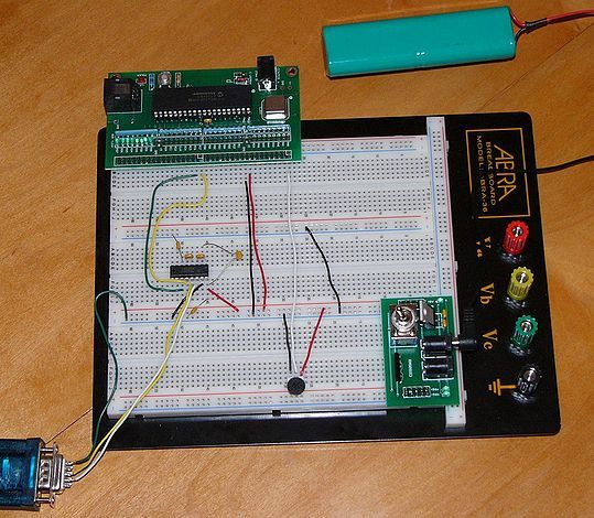
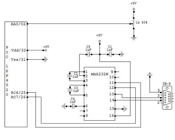
A female DB9 connector was wired to our level shifter to convert the voltages, with the level shifter connected to our PIC. The female DB9 connector is used so no wires need to be directly soldered to the serial cable. Refer to the Circuit section for details on this connection.
The PIC was programmed with our C code as shown below. Our program was designed to read a potentiometer through the PIC’s ADC (Analog to Digital Converter) port and transmit the digitized readings over the serial cable to the PC (upon request). In Matlab, if a users sends data to the PIC by entering a character, the PIC responds with the current potentiometer reading and the last received byte from the PC. The PIC is also programmed to display the character received from the PC on its LED array (D register) as a 8-bit ASCII number. The programs can easily be modified to create any custom protocol, but are designed to show simple 2-way communication between Matlab and the PIC.
Circuit
The wiring diagram for serial communication is shown below. There are three basic components in this setup. The potentiometer serves as an analog input to the PIC, which is converted to a digital signal through the PIC’s analog to digital converter pin. The MAX232N level converter provides bidirectional voltage shifting for digital communication between the PIC and PC (read more about this chip and level conversion on the RS232 wiki here). Finally, the female DB-9 connector allows the circuit to connect to the PC’s serial port.
For more detail: Serial communication with Matlab


