Summary of Schematic design with the PIC16F84A microcontroller
This article describes a flexible "knight-rider" LED light sequence circuit using a PIC16F84A microcontroller instead of the common CD4017 counter IC. Powered by 7-12V DC, it uses a 7805 voltage regulator for stable 5V output. An external RC oscillator with a 10k resistor drives the microcontroller, which controls LEDs on ports RB0-RB7, lighting two LEDs simultaneously in sequence. The LED on-time is 0.14 seconds, adjustable by changing resistor R1 or adding a capacitor. Software versions include an assembler-based simple on/off and a C-based version with PWM for LED intensity trails.
Parts used in the Knight-Rider LED Light Computer:
- PIC16F84A microcontroller
- 7805 voltage regulator
- Resistor 10k (for RC oscillator)
- Resistor R1 (timing adjustment resistor)
- External RC oscillator components (resistor and optionally capacitor)
- LEDs (connected to RB0 - RB7 ports)
- Power supply (7-12V DC)
- Zener diode (optional voltage stabilization alternative)
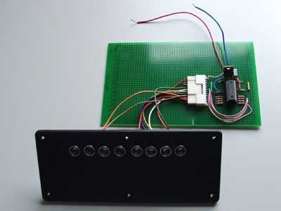
Many circuits on the Internet are built with a CD4017 counter IC. I myself chose to use a microcontroller for this job: the PIC16F84A. A microcontroller increases the complexity but it allows you to build a very flexible light computer. The circuit can be kept very small, this was a requirement for this circuit.
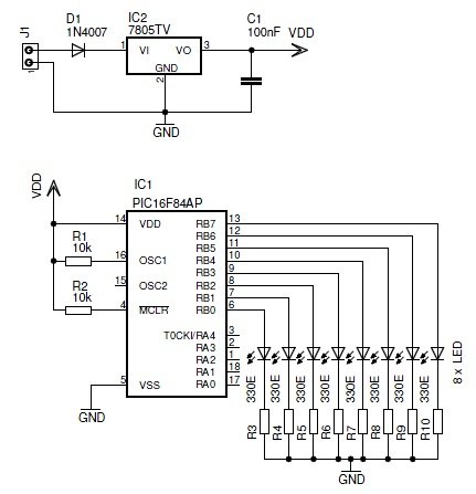
 The circuit can be powered by a DC voltage between 7 … 12 V. I used a 7805 regulator to create a stable 5 VDC voltage. It you want to keep the circuit very small you could use a zenerdiode for the stabilization.
The microcontroller is oscillated by an external RC oscillator. The capacitor was left away. This can be done but it decreases the stability of the frequency. The resistor has a value of 10k.
The microcontroller drives LEDs through output ports RB0 … RB7.. During the execution of a knightrider effect there are always 2 LEDs active at a time.
I did some measurements on the circuit and the LEDs are active for a period of 0.14 seconds. To change the speed you can simply change the value of resistor R1. You could also add a capacitor between OSC1 and the GND.
 Software Design
Over time I wrote two different versions of the software for this light computer.
- A basic version in the assembler language. It runs the knight-rider light effect with only two possible output states: ON or OFF. Download the assembler source code.
- An extended version in the C Language. This software generates a little trail before and after the active LEDs. The intensity of the LEDs in the trail is lower. This is done by implementing some sort of PWM (pulse width modulation). Download the High-TECH C source code.
For more detail: Schematic design with the PIC16F84A microcontroller