Summary of Rotary Encoder Interfacing with PIC Mirocontroller
This article discusses upgrading traditional power supply controls by replacing conventional potentiometers and rotary switches with digital Incremental Rotary Encoders. It explains the nature of these fully digital components, highlights their output waveforms, and demonstrates decoding their signals using a microcontroller via a state machine approach. A schematic featuring the PIC18F458 microcontroller is provided, alongside downloadable source code and firmware for implementation.
Parts used in the Rotary Encoder Interfacing with PIC Microcontroller project:
- Incremental Rotary Encoder
- PIC18F458 Microcontroller
- Supporting components for schematic (resistors, capacitors, etc.)
i am currently working with some power supply design and i can say using conventional pots(potentiometer) and rotary switch to adjust the voltage and other stuff is quite old school.
so i have decided to go for a bit high tech , actually bit digital.
so here is the solution
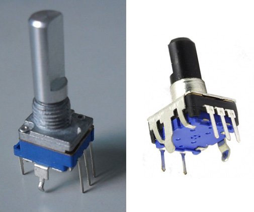
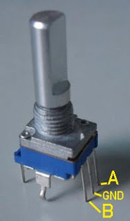
Incremental Rotary Encoder
first of all i would like to tell you , these type of rotary encoder is totally digital component so you can’t directly replace these with you conventional pots. so lets start what are Incremental Rotary Encoder ,
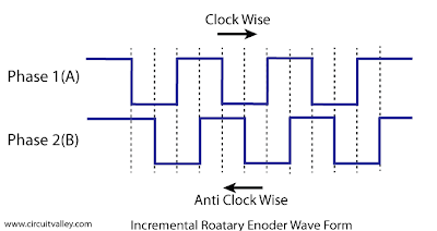
and hear the output wave form
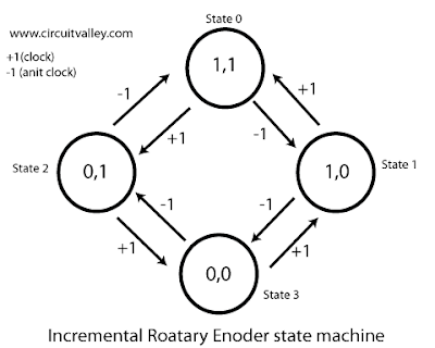
Decoding with Microcontroller
in this examples we will be decoding the rotary encoder with the help of sate machine.
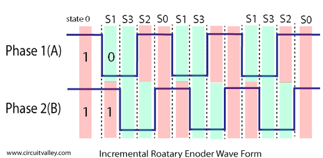
view of state machine in the wave form
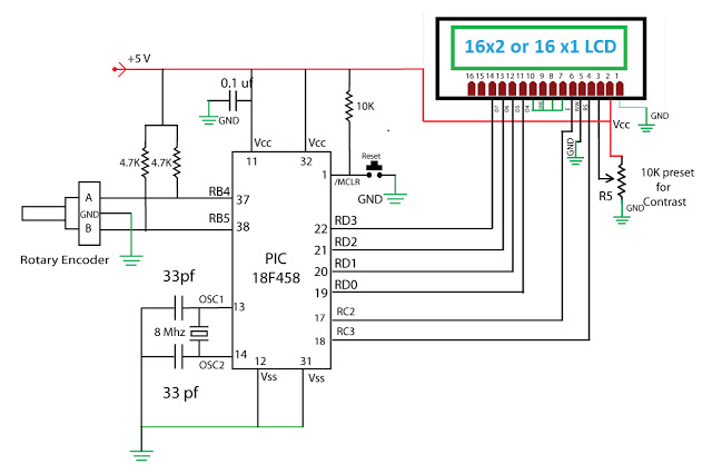
Schematic with PIC18F458
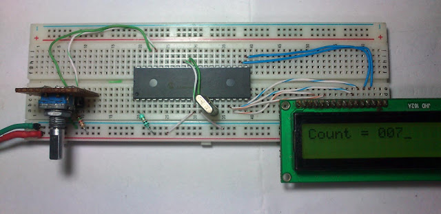
Source code and firmware
CLIK Here To download Source Code and Firmware. if you have any problem please leave in the comment section.
CLIK Here To download Source Code and Firmware. if you have any problem please leave in the comment section.