This project adapts an RGB Moodlight design to create strobe and beacon lights for model aircraft and boats. It uses a PIC microcontroller with PWM outputs to control LED brightness and sequences that simulate navigation lights. Two versions exist: a basic continuous output and a servo-controlled version that enables outputs based on servo pulse widths. The circuit is low power and easily integrated into models, powered by alkaline or rechargeable batteries. Customizable code is available for programming different light sequences.
- PIC microcontroller (IC1), e.g., PIC12F629
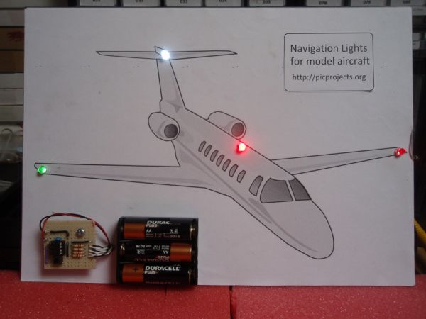
- Red, green, and white LEDs
- Resistors (270 ohms for LEDs, 1K0 for R6)
- Capacitor C1 (ceramic decoupling capacitor)
- NPN transistor Q1 (for servo pulse inversion, in servo-controlled version)
- Push-to-make switch SW1 (sequence select)
- SPST switch SW2 (power switch)
- Power supply: three 1.5V alkaline or four 1.2V NiMH batteries
Description
This project was inspired from a post on the Picprojects forum where a member had adapted the RGB Moodlight project for use as a strobe and beacon for a model aircraft.
I thought this would be of interest to others so I’ve put this page together with schematic, examples and free code download. You can also buy a PIC pre-programmed with the firmware from the Picprojects e-Shop
The sequence data has been custom written to produce the beacon and strobe light effects found on aircraft and boats.
The design has been kept as simple as possible to keep the size small and therefore easy to build into a model. The circuit has very low power consumption and can be powered from Alkaline or rechargeable batteries.
It is not necessary to use all the outputs, for example the beacon output is also very effective for use in a model Lighthouse.
For those with access to a PIC programmer the source code is available to allow you to customise the sequences and program the PIC with your own effects.
Circuit Description
The circuit use a PIC microcontroller, IC1, to drive LEDs with a pulse width modulated (PWM) signal that allows the brightness of each LED to be controlled and faded
There are a number of sequences programmed into the PIC and these can be selected by pressing the sequence select switch SW1. Each time the switch is pressed the next sequence is selected, when the last sequence has been reached it returns to the first. The selected sequence is saved to non-volatile EEPROM about 10 seconds after the switch is pressed. On power-up the last saved sequence is used.
There are two versions of this project and two versions of the firmware which can be downloaded at the bottom of the page.
Basic version: all outputs operate continually while powered on.
Servo Controlled Version: Outputs are activated under control of an RC servo pulse input. The outputs still perform the same stobe/beacon/position lights when active but can be turned off under control of the servo signal
The servo pulse is monitored on the GPIO4 input of the PIC. The signal on the PIC input needs to be active low so the NPN transistor Q1, is used to invert the normal servo pulse signal.
When the servo pulse is between:
- 1ms – 1.25ms all outputs are off
- 1.25ms – 1.5ms output GPIO2 is active
- 1.5ms – 1.75ms outputs GPIO2 and GPIO1 are active
- 1.75ms – 2ms GPIO2, GPIO1 and GPIO0 are active
Outputs
For the Model Navigation Lights project the function of the outputs is predefined.
- GPIO0 (pin 7) operates as a anti-collision beacon simulating a rotating light.
- GPIO1 (pin 6) operates as a strobe
- GPIO2 (pin 5) is driven with a constant 30% duty cycle signal for navigation lights
LEDs on GPIO2 are driven with a 30% duty cycle which reduces overall battery drain and if you want to dig into the source code and alter the sequence data (in the RCnavLightsData.inc file) you can modify the duty cycle to adjust the brightness. You could can also leave this output unused and just wire the LEDs directly across the battery (not forgetting the current limit resistors!)
The schematic shows one LED attached to each of the GPIO0 and GPIO1 outputs. You can if required add a second LED to these outputs by using a second resistor and LED as we have done with the navigation LEDs connected to GPIO2.
The resistor values shown on the schematic for the LEDs are 270 ohms. This will work for almost all types of 3/5/10mm LEDs. To increase the LED current and brightness (at the expense of battery life) you can use a lower value resistor but don’t go below 150 ohms.
LEDs
For the navigation lights shown we have used red, green and white LEDs but you can use any colour LED you want to suit your project. The PIC can directly drive (via a current limit resistor) LEDs up to 25mA per output. Most small 3/5/10mm LEDs will work. If you want to drive higher power LEDs you can use the firmware for this project with the Power MOSFET RGB LED Driver project
Capacitor C1 and Resistor R5
Capacitor C1 provides power supply decoupling. It is important this is fitted as close to the power supply pins of IC1 as possible. Ceramic capacitors come in either disc or multilayer type – multilayer ones are generally smaller but either type will work.
Resistor R5 is used to pull up the MCLR reset input on the Microcontroller. If it isn’t fitted the circuit will operate erratically or not at all.
Transistor Q1 and Resistor R6
Only used with the servo controlled version. Q1 inverts the normal active high servo pulse which is required by the PIC microcontroller. R6 is a 1K0, 0.25w resistor.
SW1 Switch
Is used to select the sequence effects. Any small push-to-make type switch should work here.
Since the last selected sequence is saved, if you are trying to keep the circuit as small as possible you can make a temporary switch connection to set the sequence you require, them remove it before building it in your model.
SW2 Power Switch
Depending on how you use this project you may be powering it from some other power source that already has a power switch. If not, you will probably want to fit a SPST (single-pole, single thow) slide or toggle switch to allow the circuit to be switched on and off.
Power Supply
The circuit as shown in the schematic draws an average current of around 7mA operating from a 4.5 volt supply.
It can be powered from three 1.5 volt alkaline batteries or four 1.2 volt NiMH rechargeable batteries. The PIC microcontroller will operate with a supply voltage from 3 volts to 5 volts but high brightness LEDs will need a minimum supply voltage of 4 volts to operate effectively. The power supply must not exceed 5 volts otherwise the PIC microcontroller may be permanently damaged.
For more detail: Navigation Lights for Models for PIC12F629