Summary of MUSIC BOX using PIC12F629 Microcontroller
This project, called EVOLUTION, combines 11 melodies into one design using a PIC12F629 microcontroller. It overcomes memory limitations by using program-space for data storage and optimizing note timing, enabling playback of multiple tunes with a single byte per note. The circuit is simple, featuring just the microcontroller, a piezo diaphragm for sound, and a pushbutton to cycle through melodies. It includes a memory feature using EEPROM to recall the last selected tune. The piezo is driven by two outputs in opposite phases to amplify sound volume.
Parts used in the EVOLUTION project:
- PIC12F629 Microcontroller
- Piezo diaphragm
- Pushbutton switch
- Prototype PC board or matrix board (for assembly)
- Fine tinned copper wire (for wiring on matrix board)
- Battery snap (for 9V battery, in Version 2 kit)
- Three LEDs (for voltage regulation and ON indicator, in Version 2 kit)
- 9V Battery (power source)
This project is an extension of a number of musical projects (Happy Birthday and It’s a Small World) and puts 11 melodies into a single design.
It’s called EVOLUTION.
From the previous projects we learnt a lot about producing a tune.
The first thing we learnt: it takes a lot of memory.
Each note needs one, two, or even three bytes and this severely limits the length of the tune, as the PIC12F629 has a maximum of 256 bytes for a table and this can only be placed in the first page of memory (the chip does not have the facility to access a table in any other part of memory).
We had to re-design the program so all of the 1024 locations of program-space could be used.
This was done by omitting tables and using the program-space for the data-bytes.
We reduced the data-requirement further by requiring only a single byte to produce the length of the HIGH. The length of the LOW was obviously the same duration.
But now we had a problem.
To produce a note of say 300mS, we had to supply data for the number of cycles. Obviously a high frequency needs more cycles for 300mS, than a low-frequency note.
The answer was to complement the data-bye.
This produced a result very near to 300mS.
The only other thing we had to produce was a note of a suitable length.
This was done by shifting the file right (rrf) to get a value of 50% and adding it to the original value, plus performing other operations to generate the correct length.
This has changed the capacity of the project from 2 tunes to 11, with NO bytes to spare. You cannot use location 3FF for your program as it is used by the micro to store the oscillator value.
We have also included a button to increment through the tunes.
When the project is first turned on, it will play each tune twice. If the switch is pressed, the project will go to the first tune and it will be repeated. If it is pressed again, the second tune will be selected and repeated. See below for more details on this.
The melodies are recognisable but some of the notes are very hard to reproduce in monotone and we have left it up to an aspiring musical person to alter the tones to create an improvement.
THE CIRCUIT
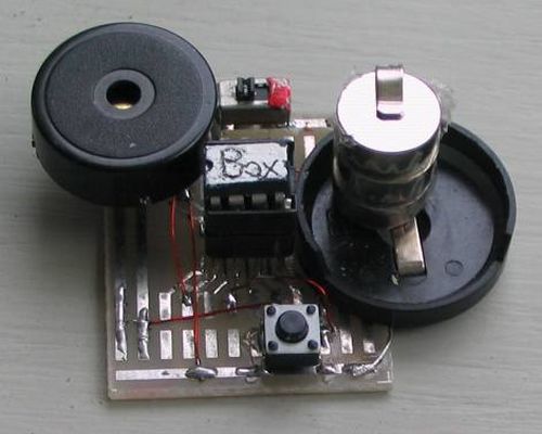
The circuit uses just a few components on a small prototype PC board. It’s easy to construct and ideal for a beginner. It’s just a PIC chip, a piezo diaphragm and a switch. You can put it together in a few minutes on a prototype board and download the program from the website.
The pull-up resistor for the switch is inside the chip and this saves one component. We have not placed a 100n across the chip and this is another component saved. The circuit takes less than 1mA and everything else is inside the chip via a program.
The photo shows the prototype.
If you want to buy a kits, there are two versions:
Version 1 comes as a piece of matrix board consisting of solder lands. After placing and soldering the components to the lands, they are joined with fine tinned copper wire to represent the tracks of a printed circuit board.
Version 2 has a PC board and a battery snap for a 9v battery. Three LEDs on the board regulate the voltage to 5v and also act as an “ON” indicator.
Music Box has a memory feature. Any of the tunes can be selected and when the project is turned on again, the selected melody will repeat.
Simply increment through the melodies via the button and turn the project off. Turn the project on to hear the selected melody.
To erase the selection, push the button when the project is off and turn it on. Release the button immediately and the program will start at the first melody and play each twice.
This feature uses the EEPROM and the program below shows exactly how to use these instructions to perform read and write operations.
When creating your own program, these instructions should always be copied and pasted to prevent a mistake.
The full 1024 program locations have been used in this project plus the first location in EEPROM.
PRODUCING A TONE
Producing a tone is very easy. All you have to do is make an output go HIGH then LOW at a controlled rate.
The output goes HIGH and stays HIGH for a certain number of microseconds then goes LOW and stays LOW for the same time. If the HIGH and LOW times are not the same, the tone is not very “clean” and does not have a “ring” about it.
In our case, we have connected the piezo diaphragm to two outputs to increase the volume.
When one output goes HIGH the other goes LOW and vise versa. This causes the piezo to see an increased voltage because the piezo is actually a capacitor of about 22n and when it gets a voltage on one direction, it charges to a voltage equal to the applied voltage.
To make the discussion easy to understand, let’s say one lead is fixed at 0v, and the other lead is now supplied with a reverse voltage. The potential of the other lead will change from say a positive voltage to a negative voltage. This is a swing of twice the value of the supply and the additional voltage produces a louder output.
For more detail: MUSIC BOX using PIC12F629 Microcontroller