Summary of Multipulxing 7 Segment Display using PIC18F2550 Microcontroller
This tutorial explains designing a decimal counter from 0000 to 9999 on multiplexed common cathode seven-segment displays using the PIC18F2550 microcontroller in Proteus ISIS. It details multiplexing to reduce I/O pins by activating one digit at a time rapidly, utilizing NPN transistors to select digits. The firmware, written in C with MikroC Pro, uses a timer interrupt to cycle through digits and display the count, incrementing every 400 ms. The setup enables clear visualization via persistence of vision and is ideal for compact numeric displays.
Parts used in the Decimal Counter with Multiplexed 7-Segment Display:
- PIC18F2550 Microcontroller
- Common Cathode 7-Segment Displays (4 units)
- NPN Transistors (4 units)
- Resistors (for base current limiting of transistors and segment current limiting)
- Connecting wires
- Power supply (suitable voltage for PIC and displays)
- Proteus ISIS software (for simulation)
- MikroC Pro for PIC compiler
This tutorial describes how to implement decimal counter which will increment from 0000 to 9999 ; in multiplexed seven segment display using PIC18F2550 in PROTEUS ISIS.
Multiplexing is required when we want to interface 3 or 4 or even more such displays with MCU ssince it we go for normal way it will require lots of IO port.This means to turn on one at a time, extra brightly, and scan through all the digits fast enough that the eye blurs the ON and OFF.
Whatis a Seven Segment Display ?
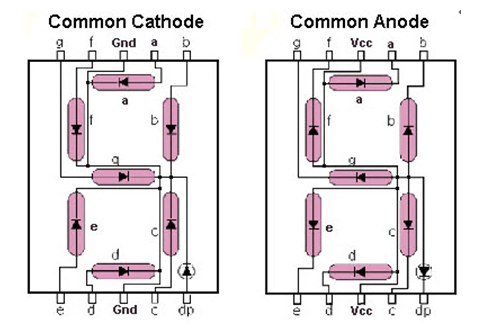
A Seven Segment Display (SSD) is one of the most common, cheap and simple to use display. Seven Segment Displays are of two types :
Common cathode : In the common cathode type SSD, the –ve terminal of all the LEDs are commonly connected to the ‘COM’ pin. A segment can be lighted up when ‘1’ is given to the respective LED segment and ground is connected to the common.
Common anode : In the common anode type SSD, the +ve terminal of all the LEDs are commonly connected to the ‘COM’ port of the SSD. A segment can be lighted up when the ‘COM’ port is connected to the +ve battery supply, and ground is given to the respective segment.
It looks like this :
For more information about seven segment https://www.electronify.org/basic-component-introduction/seven-segment-interface
Description :
All the similar segments of multiple LED displays are connected together and driven through a single I/O pin.
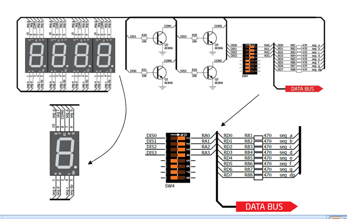
Instead, 4 NPN transistors are used as switches to connect or disconnect the cathode terminals from Gnd. When the base of the NPN transistor is high, the transistor conducts and corresponding digit’s common cathode is connected to GND. Therefore, the transistor selects which displays is active. The conduction of the transistors are controlled by RA0 through RA3 pins of PORTA. Suppose, if we want to display 7 in the units digit place, then segments a, b, and c should be turned on first (which means RB0, RB1, RB2 are 1 and RB3-RB6 are 0) and then RA0 should be pulled up (while keeping RA1-RA3 low) so that only units digit display will be active. In order to display all 4 digits, each seven-segment display is activated sequentially using an appropriate refresh frequency so that it will appear that all the them are turned on at the same time.
We have four 7-segment displays connected to the same PORTB on the PIC18F2550. Because the circuit is connected in this way we have to multiplex the output.
switch on display 1 and switch off the other 3 displays (2, 3,4)
switch on display 2 and switch off the other 3 displays (1, 3,4)
switch on display 3 and switch off the other 3 displays (1, 2,4)
switch on display 4 and switch off the other 3 displays (1, 2,3)
Decoding Function :
function which will return Seven Segment Decoded mask of a single digit.
Multipulxing 7 Segment Display using PIC18F2550 Microcontroller (Code)
unsignedintmask(int a)

{

switch(a)

{

case 1: return 0x06;

case 2: return 0x5B;

case 3: return 0x4F;

case 4: return 0x66;

case 5: return 0x6D;

case 6: return 0x7D;

case 7: return 0x07;

case 8: return 0x7F;

case 9: return 0x6F;

case 0: return 0x3F;

}

}
Software :
The firmware is written in C and compiled with MikroC Pro for PIC V7.1.0.
Download crack version :https://www.facebook.com/groups/816450708460518/1123157827789803/
CODE :
#include "Display_Utils.h"

unsigned short shifter, portb_index;

unsigned int digit, number;

unsigned short portb_array[4];

void interrupt() {

PORTA = 0; // Turn off all 7seg displays

PORTB = portb_array[portb_index]; // bring appropriate value to PORTD

PORTA = shifter; // turn on appropriate 7seg. display

// move shifter to next digit

shifter <<= 1; if (shifter > 8u)

shifter = 1;

// increment portd_index

portb_index++ ;

if (portb_index > 3u)

portb_index = 0; // turn on 1st, turn off 2nd 7seg.

TMR0L = 0; // reset TIMER0 value

TMR0IF_bit = 0; // Clear TMR0IF

}

void main() {

ADCON1 =0x0F; // Configure PORTX pins as digital

CMCON = 0x07; // comparators OFF

TRISA = 0; // Configure PORTA as output

PORTA = 0; // Clear PORTA

TRISB = 0; // Configure PORTD as output

PORTB = 0; // Clear PORTD

T0CON = 0xC4; // Set TMR0 in 8bit mode, assign prescaler to TMR0

TMR0L = 0; // clear TMROL

digit = 0;

portb_index = 0;

shifter = 1;

number = 9980; // Initial number value

GIE_bit = 1;

TMR0IE_bit = 1;

do {

digit = number / 1000u ; // extract thousands digit

portb_array[3] = conversion(digit); // and store it to PORTD array

digit = (number / 100u) % 10u; // extract hundreds digit

portb_array[2] = conversion(digit); // and store it to PORTD array

digit = (number / 10u) % 10u; // extract tens digit

portb_array[1] = conversion(digit); // and store it to PORTD array

digit = number % 10u; // extract ones digit

portb_array[0] = conversion(digit); // and store it to PORTD array

Delay_ms(400); // one second delay

number++ ; // increment number

if (number > 9999u)

number = 0;

} while(1); // endless loop

}
Multipulxing 7 Segment Display using PIC18F2550 Microcontroller (Schematic Diagram)

Results :
After the c code is successfully compiled, a HEX file is generated.For simulating with PROTEUS ISIS hit run button and and then you will get above output.
we can drive more than one Seven Segment Display by using a technique called ‘Multiplexing’. This technique is based on the principle of Persistence of Vision of our eyes. If the frames change at a rate of 25 (or more) frames per second, human eye can’t detect that visual change. Each display is turned on above this rate and our eyes will think that the display is turned on for whole the time.
We have used Common Cathode Seven Segment Display in this example. Pins RD0 – RD6 are connected to the A – G of the display. This will count from 0000 to 9999.
Resource :
You can download the MikroC Source Code and Proteus files etc from here download
The same application with PIC16F877A :https://drive.google.com/file/d/0B2IMfviPpUnLeWlJbHZHNnpEY1k/view
This Our Group (thanks to join and participate) : https://www.facebook.com/groups/816450708460518/
Facebook page (thanks to join and share) :
https://www.facebook.com/Lets-Think-Binary-1728910547340654/
Youtube Channel (thanks to subscribe) :