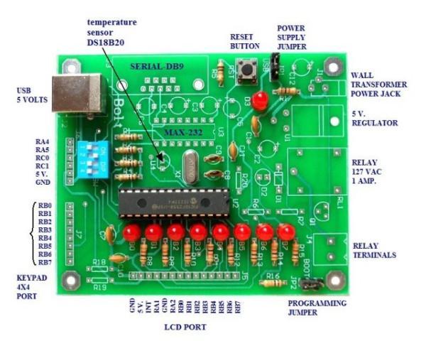
The BOLT microcontroller board utilizes the Microchip 18F2550 with built in USB capabilities. Utilizing a 2k ‘boot loader’ this leaves a great deal of flash RAM for C programming using MPLAB and the C18 compiler. The BOLT board comes in two versions. LITE which has the 18F2550, 8 LEDs for PORTB, four switches and a USB 2.0 port connection to a PC. Operating with a 20 mHz crystal, by use of internal multipliers operates at 48 mHz.
 The full version has additional components including a relay, DS18B20 temperature sensor, RS232, etc. I went with the LITE version and added my own 90 degree header pins. The idea was to port over my Arduino projects to PIC C and learn how to program PICs. The BOLT comes with a lot of working examples in both assembly and C to gives the novice a place to start.
The system is powerful and inexpensive. With the LITE version at $15 which includes the 18F2550 it requires no external PIC programmer just a USB cable. This is right in the price range of an Arduino at three times the speed. While I’m using the 28-pin version, there’s a 40-pin version with more I/O.
In comparison to Arduino I’d advise against using a PIC starting out without some electronics and C programming knowledge. One will also need to understand and setup MPLAB and understand the C18 compiler libraries which can be very valuable. While having a steeper learning curve than Arduino, it has greater versatility and potential.
The website for the BOLT is at http://www.puntoflotante.net/BOLT-SYSTEM.htm in Mexico. Be warned some of the notes in the examples are in Spanish but are fairly self-explanatory. I’m including ZIP files with the BOLT template which includes linker file and several H files for ADC, serial, and One-Wire. I also include most of the examples.
The PIC18F2550 has 32k of flash (2k used by boot loader), 2k of SRAM, 256 bytes of EEPROM, 24 I/O pins, 10 10-bit ADC channels, 2 PWM, USART, USB 2.0, etc. This is a RISC processor with 75 instructions and is ‘optimized’ for a C compiler.
Below are a listing of my recent projects ported over mostly from my Arduino projects and some extra. I have my own code and H files depending on what hardware one wants to attach to the system. My LCD routines are for use with my serial 74164 LCD project from Arduino.
 See Connect Arduino to LCD Display with 74164 Shift Register
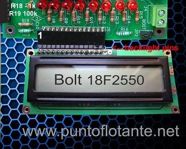
The board can use a common HD44780 directly connected to BOLT as shown above. Two resistors must be added: R18 is 1k and R19 is 100k. Notice the two backlight pins are disconnected. If one’s display requires a backlight (mine did being blue) then solder a jumper from pin 15 (anode) to +5 volts (or pin 2) and pin 16 (cathode or K) to GND or pin 1.
In my case I soldered in a 5k potentiometer replacing R18/R19 to better adjust contrast.
There are two ways to connect the LCD display to BOLT either parallel as shown above or with my serial LCD project ported over from my Arduino project.
For more detail: Introducing the BOLT PIC18F2550 Microcontroller Board