How to build your own PIC-Programmer using PIC12C50x

Summary of How to build your own PIC-Programmer using PIC12C50x


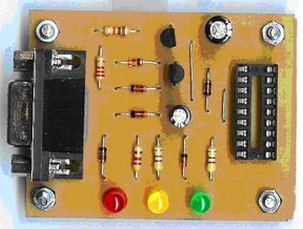
This PIC-Burner supports PIC12C50x, PIC12F62x, PIC16FFxx, PIC16F62x microcontrollers, and EEPROM 24Cxx. It is tested on models like PIC12C508(A), PIC12C509(A), PIC12F629, PIC12F675, PIC16F84A, PIC16F627, and PIC16F628. The programmer is compact (50mm x 62mm) and uses three LEDs to indicate burn status. A modification to the JDM-Programmer allows programming PICs with LVP function by connecting pin 10 to Vss instead of VDD. The schematic was designed using Eagle-Lite, and uses common components like NPN transistors, 16V capacitors, a 9-pin female SUB-D connector, and standard resistors.

Parts used in the PIC-Burner project:

  • PIC Microcontrollers (PIC12C50x, PIC12F62x, PIC16FFxx, PIC16F62x)
  • EEPROM 24Cxx
  • 3 LEDs (Red, Yellow, Green)
  • Bipolar NPN transistors (small signal types)
  • Capacitors (16 Volt types)
  • 9-pin female SUB-D connector (Reichelt EMV-BUCHSE 09W)
  • Resistors (1/4 Watt, 5% tolerance)

Which types of PIC microcontrollers and EPROM’s are supported?

You can use this PIC-Burner for PIC12C50x, PIC12F62x, PIC16FFxx, PIC16F62x and EEPROM 24Cxx. This PIC-Programmer was tested with PIC12C508 (A), PIC12C509 (A), PIC12F629, PIC12F675, PIC16F84A, PIC16F627, and PIC16F628.
The PIC-programmer is easy to build and compact. 3 LEDs indicates the state of the burning-process. Red: burning, yellow: clock-signal, green: power supply. The dimensions are about 50 mm x 62 mm.
PIC-Programmer

The Modification of this JDM-Programmer:

In comparison to the original JDM-Programmer exists a connection between pin 10 (JDM) and Vss instead of VDD. This modification makes it possible to program PIC microcontrollers with LVP-function (for example PIC16F627 or PIC16F628).

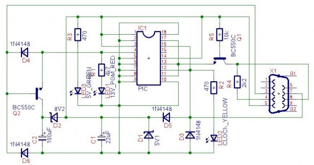
The Schematic of the PIC-Programmer:

The wiring diagram was drawn with Eagle-Lite by CadSoft in order to create a print layout by my self. Eagle is very popular print layout software in Germany and for non-commercial use free.

The schematic view of the PIC-Programmer (http://www.janson-soft.de/pic/parts-and-hints.txt). The bipolar npn-transistors are not very critical. Probably you can choose almost any small signal types. The capacitors are 16 Volts types. The SUB-D-connector is female and has 9 Pins (Reichelt-Best.-Nr.: EMV-BUCHSE 09W). All resistors are common and have 1/4 Watts, 5% tolerance (Download of the Eagle-SCH-file for the schematic here).
Schematic PIC-Programmer

http://www.janson-soft.de/pic/jdm-schematic.sch

The Print Layout:
I developed the print layout with the help of Eagle. Because I am not a professional lay outer I used the auto router. After some tries and errors I came to a practical solution for homebrewed stuff. My intention was not to build something for the industrial mass production.


For more detail: How to build your own PIC-Programmer using PIC12C50x


About The Author

Ibrar Ayyub

I am an experienced technical writer holding a Master's degree in computer science from BZU Multan, Pakistan University. With a background spanning various industries, particularly in home automation and engineering, I have honed my skills in crafting clear and concise content. Proficient in leveraging infographics and diagrams, I strive to simplify complex concepts for readers. My strength lies in thorough research and presenting information in a structured and logical format.

Follow Us:
LinkedinTwitter

Leave a Comment

Your email address will not be published. Required fields are marked *

This site uses Akismet to reduce spam. Learn how your comment data is processed.