Introduction The objectives of the FailureBot project originated simply as “build a line-following robot”. However, it somehow evolved into a 3-year robotics experiment. My first attempt to build a robot was such a complete failure that I jokingly called it “FailureBot”. The name seemed quite appropriate even as the project evolved as every one of the many, many failures yielded a critical lesson in the robot-building process. For me, hobby robotics is about creativity. I didn’t want to throw a couple sensors on a robot kit, I wanted to build it from the ground up. Looking through catalogs, reading datasheets, and building the robot within the constraints of my limited resources was the ultimate experience. Much of this robot is built from raw materials and hardware available at local hardware stores– and done so on a very limited budget. Throughout the process, I kept a couple of concepts in mind:
- Close enough is good enough. I’m not a NASA engineer, I’m a hobbyist. It doesn’t have to be perfect, it just has to work. This is especially true considering that my “workshop” is merely a bedroom floor and a Dremel rotary tool. I don’t have the facilities to make straight cuts or aligned holes. Improvise.
- The overall goal is to learn and discover. When it felt like I was re-inventing the wheel I just reminded myself that I was learning how the wheel was invented.
- Success is a series of failures. It can be very discouraging to spend large amounts of time only to hit a dead-end and start over. This is FailureBot 5 because I’ve had to start over from scratch 5 times with the physical construction. The lessons learned made it very much worth while.
- Work within your means. I would often get discouraged by what I see other people building–making molds, welding, etc. I don’t have those resources nor a large budget. A roboticist shouldn’t be thinking about how it is supposed to be done, but how it could be done considering the elements.

Line Following Robots
A line-following robot, or “line follower” is a pretty common type of robot for hobbyists. Robotics competitions usually have a line-following event. The line is usually a black line about 3/4″ wide, such as black electrical tape, on a white surface. Advanced courses may add new challenges such as inclines, tighter turns, intersections, thinner lines, or changing line colors. The robots typically sense the line by measuring light reflected off the ground, where a black line reflects little/no light and the white floor reflects a lot of light back.There are TONS of websites relating to line-following robots as it’s a very common beginner project. The Robot Room has some great information on a couple of line following robots.
FailureBot 5 Overview
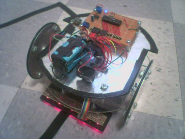
FailureBot 5 is actually a fairly good robot base which could easily be adapted to maze solving, obstacle avoiding, or other applications of a small, 2-wheeled robots. However, at this point in time, it only follows a line. The robot consists of 2 plastic round decks, differential drive using 2 DC gearhead motors, a sensor board with 5 photo-transistor/LED sensors, an L293D H-Bridge motor controller board, and an Atmel ATMega8 processor board.
A sensor board with 5 sensors shines light downward at the ground. If the line is underneath the sensor, then the little/no light will be reflected back to a paired phototransistor. If the line is not underneath the sensor, more of the light will be reflected back. A microcontroller measures the output of each of the phototransistors through it’s analog-to-digital converter (ADC). Based on the position of the line underneath the robot, the microcontroller adjusts the speed/direction of the DC motors to steer the robot.
Building FailureBot 5
Building the robot was the hardest part for me. I am by no means a mechanical engineer and had a lot to learn. FailureBot 5 is a round, 2-deck, 2-wheeled differential-drive robot. A differential-drive robot works like a tank. The two wheels provide both the drive and the steering. By stopping one motor and not the other, the robot pivots on the stopped motor to turn. By turning one motor forward and the other motor backward, the robot turns in place. The wheels are offset forward slightly and a caster is placed in the back of the robot for support.
The Base and Second Deck
The base and second deck are 0.118″ thick x 6″ diameter Acrylic Circles purchase from Tap Plastics for $1.95 ea. They were cut to allow the wheels to be mounted within the diameter of the acrylic circles. The cutting as well as drilling holes for mounting motors and electronics was all done with a Dremel rotary tool. A piece of paper with drill/cut marks was taped over the acrylic circle as a guide for cutting. A piece of aluminum foil was also taped to the under-side of the second deck and connected to ground to serve as a sheild between the motors and the processor board. The decks are connected to each other using 4″ 6-32 screws with 6-32 hex standoffs spacing the 2 decks apart. I have no idea where I got the hex standoffs, but I’m sure they’re pretty common.
Motors and Wheels
In earlier attempts I had problems with motors not having enough torque to properly move the heavy robot bases I was building. I decided to buy gearhead motors with a very high torque and use larger wheels to make up for the loss in RPMs. There are 2 Lynx Motion Planetary Gear Motors (12vdc 189:1 31rpm) ($11.40/ea) which drive the two wheels. Each wheel is made out of two 4″ round discs bolted together with 2 washers spacing them out. The discs are from Home Depot ($1.49/ea) which are used to cover electrical boxes. A 4″ O-ring (also from Home Depot) sits in the gap between the two discs to serve as tires. These relatively large wheels allow the slower motors to suffice for moving the robot quickly. They are also nice and thin giving the robot the ability to easily turn by pivoting on one wheel. The wheels were then attached to the motors using a pair of the 6mm Universal Wheel Hubs from Lynxmotion ($8.00). The motors are then mounted to the base using a homemade motor mount. Although Lynxmotion also sells motor mounts, I had already felt I had spent enough money on the motors. Home Depot (or Lowes, etc) has a section with weather stripping including long pieces of aluminum in various shapes and thicknesses. I picked up a right angle strip (4″ wide piece of aluminum folded at 90 degrees) and cut it up using–once again–the Dremel rotary tool. The motors are mounted slightly forward from the center-line of the robot and a caster from Home Depot ($2.95) was mounted in the back/center of the robot.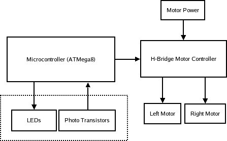
Sensor Board
The sensor board was one of the only things that worked since the very first FailureBot. There are 5 line sensors. Each line sensor consists of a single red LED and a photo-transistor. The electronics of the sensor board will be discussed later. However, the construction here does make a difference. The phototransistors will be sensitive to the ambient light in the environment and thus I want to keep that down to a minumum. I want the light from the LEDs bouncing off the ground back to the phototransistor to be the primary light hitting the phototransistor. I used a piece of acrylic plastic (Home Depot and Lowes sell acrylic rectangles for a few bucks) which I spray painted black in numerous thin coats to ensure that it was opaque. Then, holes are drilled for the LEDs and photo transistors such that the LEDs protrude out and the phototransistors are set in a bit (see my sketch below). I wasn’t too concerned with one sensor being skewed or protruding more/less as I knew I could have each LED independently calibrated via software (discussed later). Finally, two 3″ 6-32 screws with locknuts and wingnuts are used to attach the sensor board to the robot. This way, I can adjust the distance of the sensors to the ground manually by moving the locknut up/down.
For more detail: FailureBot 5 – A Line Following Robot