The goal of the electrical design was to streamline an automatic shift control while keeping manual user input in a fast, user-friendly way, incorporating Advanced Electrical Subsystem Control.
The electrical design was driven by the complexity required by the mechanical system. The system takes in rider input in the form of a throttle position sensor, shift pushbuttons, and mode selector. It also takes in other input that the rider doesn’t have direct control over; an RPM sensor and the transmission switch for detecting gear position.
Outputs consist of drivers for the solenoid (up and down) and the spark cut output.
System Level Schematic
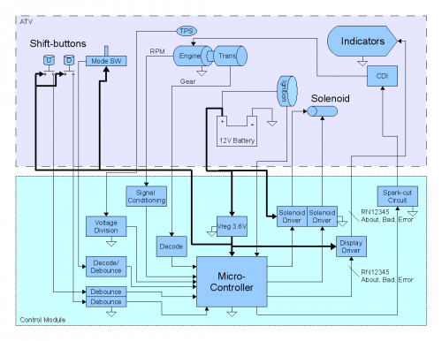
The above diagram shows the system level electrical connections from the control board to the ATV. These connections were developed from the designed controller to meet the customer needs.
Microcontroller Schematic
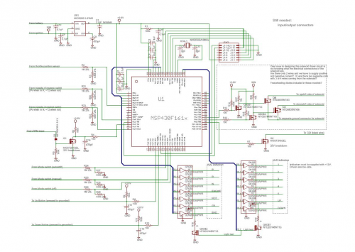
- The Processor
The MSP430 family of processors was reused from the previous year.
- 16-bit microcontroller unit, MSP430F1610
- C compilers available for easier and faster code development than assembly.
- Enough inputs/outputs to cover all required sensors/inputs and outputs required by the design.
- Low voltage @ 3.6V, low current @ <25mA. Low-power requirements to ease energy budget on the ATV.
- 8 MHz external clock for heavy math calculations and fast ADC samplings.
- 16 interrupt vectors to handle asynchronous inputs/outputs.
- On-board peripherals such as ADC (for TPS), 2 timers/CCPs (shift timing), hardware mult. (math calcs)
- Board Power Supply
- 500mA, 3.6V LDO linear regulator (MIC5219) step-down from 12V ATV battery
- On/off control by ignition switch input.
- Inputs
- Throttle position sensor from ATV ranges from 0-12V, so a voltage divider moves the range of voltage into the MSP430 to 0-3.6V. Sampled by ADC.
- Pushbutton switches from handlebars are hardware debounced using resistor-capacitor network.
- Mode switch is divided down from 12V by voltage divider. Common on switch is connected to 12V supply externally.
- Transmission switch senses when ATV is in Neutral or Reverse or neither. Also is divided down from 12V input.
- RPM input blocks all noise below 5.1V by zener diode. Typical RPM input voltage level is an 8V square wave.
- Outputs
- Solenoid low-side (connects to ground) drivers for upshift/downshift. Capable of >40A peak.
- Spark cut low-side driver connecting to CDI module.
- Indicators of display are driven by low-side array.
1, 2 outputs are switched on and off by timerB internal to MSP430.
Read More: Electrical_Subsystem