As per the title of this question i’m trying to control an ac resistive load. So far i had little success and i’m experiencing “strange”, to me at least, behaviour from the triac(s) i tried. first of all i post a schematic of my test circuit (bare with it, it’s not a complete schematic, it represents only the control part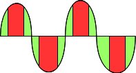
as you can see it’s sized for a 220v ac line missing in the schematic is a quadrature encoder input used to control the delay of the firing pulse to the opto. What i did is take the zero cross signal and compute a delay based on the encoder input (ie if the input was 5 out of 10 i’d start a timer on ZCD and once it reaches 5 it would trigger the opto led thus triggering the BTA10 triac) So far so good, the ZCD outputs a nice spike which is read by the pic and the output to the MOC is perfectly timed. Now comes the problems. Just to test the circuit i tried first with 15vAC (sizing the resistors accordingly and using a couple of car tail lights as a load) and i experienced this
problem
ok, i don’t draw very well…what was happening was that the triac switched nicely in the green region and won’t turn on at all in the red one. i was puzzled but i thought it could be a voltage problem so i went from 15v to 110vAC (again changing the resistors and load). Now the triac switched on only at the very beginning of each half wave right after ZC. Sometimes switching only one half of the full wave.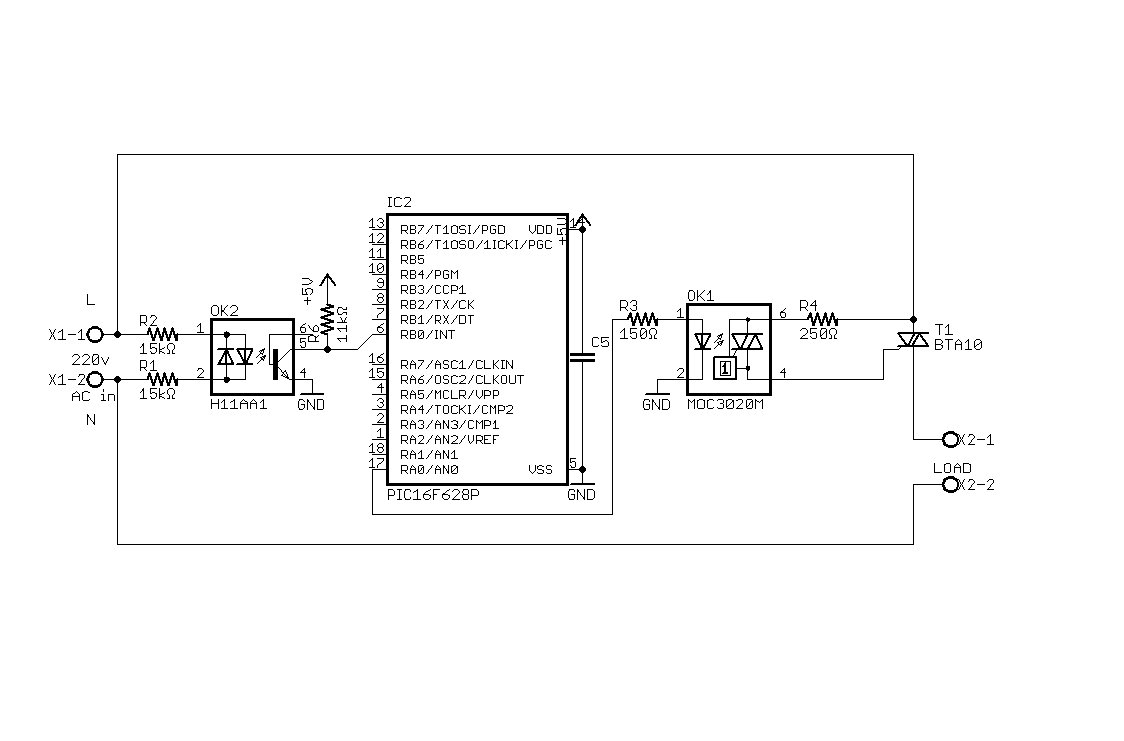 As soon as i delay my triggering signal more than a few hundreds uS or so the triac just stops working. I also changed the load to a beefier one (a heater) to increase current but nothing happened. I also tried playing with the resistors a bit to see if i can get some changes but had no luck. Now reading some forums I thought I may get rid of the transformer i used to supply my circuit with 15vAC first and 110vAC after and connect everything directly to the mains as it will eventually be. But maybe someone can point me directly to the correct answer! May the transformer be the culprit? If not what can it be? I don’t have much experience with TRIACS so my knowledge is surely lacking something and i may have forgot something important in the description of what I’m doing that can be helpful to get the answer right… Just to be sure i link here the datasheets of the triac, optocoupler and optotriac. And an app note with some of the calculations i’ve used.
For more detail: Control AC load with microcontroller.