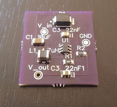
Step 1: Gather the Materials!
So with any prototyping project this really shouldn’t be the first step… But we’re gonna go ahead and do it cuz it’s just so darn fun! Just a little disclosure, we’ll be using the ACT4088 picked because it’s cheap and has an adjustable VOut along with a max of 1.5A out. Of course if you need different characteristics chances are, there’s a chip out there for you! The circuit we’ll build is taken straight from the IC’s datasheet and works very well!
List of parts:
- ACT4088 – http://www.mouser.com/ProductDetail/Active-Semi/AC…
- 4.7 uH Inductor – http://www.mouser.com/ProductDetail/Murata-Electro…
- Schottky Diode – http://www.mouser.com/ProductDetail/Vishay-Semicon…
- 10 uF Capacitor – http://www.mouser.com/ProductDetail/AVX/08053D106K…
- 22 nF Capacitor – http://www.mouser.com/ProductDetail/Vishay-Vitramo…
- 22 uF Capacitor – http://www.mouser.com/ProductDetail/AVX/08056D226M…
- 49.9 kΩ Resistor –http://www.mouser.com/ProductDetail/Vishay-Dale/CR…
- 16.2 kΩ Resistor –http://www.mouser.com/ProductDetail/Vishay-Dale/CR…
 Notes: Alright, now to address some design notes.
- All parts are surface mount for two reasons. 1: Our project will take up much less space once completed. 2: SMD parts are generally cheaper nowadays. 😛
- The inductor listed is shielded as speced in the datasheet however I got an unshielded one and the circuit works just as well and it’s about $0.20 cheaper.
- The two resistors listed are speced for a 3.3V out however you are more than welcomed to change them to whatever values you want! The resistor selection is how you change VOut to whatever is desired. The datasheet recommends keeping the 49.9 kΩ resistor and changing the 16.2 kΩ resistor. This being said with a little imagining you can see how a potentiometer can be used to make your very own $2 variable power supply! Which I have done and will show you at the end of this instructable.
Step 2: Design the Layout
Alright, so now let’s design the layout for the circuit we’ll be using for the Buck Converter! Don’t worry, it’s a very simple circuit and we’ll be getting the design straight from the datasheet. This is “v1.0” of my design and have thoughts for a “v1.1” I’ll share at the end! My goal when designing the layout was to fit it within a 1 square in. board which it does easily!
I use a software called DipTrace. For me it’s easy to use and has a very large library to choose parts from! Though if you do have a part that’s not listed (as I encountered when placing a WT32 bluetooth module) you can easily add it to the user library. For this circuit even though the ACT4088 doesn’t have a part listed it does use a standard footprint layout that is included in the DipTrace library, so that’s what I used and it fits perfectly! If you would rather use some other layout program such as EagleCAD or other software you can absolutely use it, I just don’t have any project files for any other program besides DipTrace.
Step 3: Order Your Boards!
Alright so now that we have our board layout design let’s upload them to a manufacturing company! For this project I used OSH Park. They do a fantastic job and offer some great services at some really great prices! They are particularly suitable for small board orders and they are run out of the US too!. the boards cost me around $1.30 a board and had to order in muliples of 3… so I got 9. lol. Another fantastic feature is that they gold plate all the contacts, pads, and holes making it ideal to solder to and gives the board an excellent finish. Also the dark purple they use for their solder mask is sick looking!
The order took about a week and a half to get to me with no delays, free shipping, and usps so no need to be there to sign! (the signing for packages thing may be one of my soap-boxes that I will save for another time)
For mroe detail: Buck Converter (DC-DC)
