


Summary of How to drive a Dot Matrix LED Display. using pic microcontroller
This article explains how to drive a 64-LED (8x8) dot matrix display using only 10 microcontroller pins by employing multiplexing and persistence of vision. By rapidly cycling through rows and columns, the human eye perceives a continuous image without flicker. The project utilizes a pre-wired LED module or custom wiring with an 8-bit PIC microcontroller (16F88/16F84), controlled via MikroC compiler software.Parts used in the Dot Matrix LED Display Project:
- Red 8x8 LEDs dot matrix display
- Mikroelectronika MikroC Compiler
- PIC Microcontroller (16F88 or 16F84)
Here you can find out how to drive an led dot matrix with 64 LEDs (8 rows by 8 columns - 8x8 display) or less e.g. 35 LEDs (7 rows by 5 columns - 5x7 dot matrix). However the principle remains the same for larger displays - you may need more processing power and driver circuitry though.
It uses persistence of vision to let you drive the 64 LED matrix with only 10 microcontroller outputs!
Normally you would need 64 outputs for 64 LEDs but by using multiplexing and a helper chip you can get away with 10.
LED Display multiplexing simply means turning on one led for a short period of time and doing this repeatedly for each LED.
If you do this fast enough then your eye will not notice any flicker.
Note: The unit used in this project is simply an array of
 Specification
| dot matrix led display driver | Red 8x8 LEDs |
Dot matrix LED display project details.
| Compiler | Mikroelectronika MikroC Compiler Free! |
| Target | 16F88/16F84 (retargetable to other PICs that have an enough pins). |
| Software level | Easy. |
| Software notes | Multiplexing the display. |
| Hardware level | Easy. |
| Hardware notes | No special notes |
| Project version | 1.04 |
| Project files | Enter your details to get the Download Link and get the microcontroller newsletter: (Your email is safe it will never be sold or rented). Note: Check your email for the project code download link. |
Multiplexing
If you tried to drive 64 individual LEDs you would need 64 individual output pins (each led connected to a output pin on one side and ground on the other).
Obviously that is a tall order so the way round it is to use persistence of vision which is a way of describing how your eye works.
Your eye reacts slowly to changes in light intensity so that if a light is turned on and off quickly enough then it does not notice that the light is off. Basically your eye remembers a light pulse for a short time.
The approximate time is 20ms so if the light is turned on at a frequency >50Hz (1/20ms) then your eye will not notice any flicker at all.
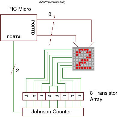
 Multiplexing uses this fact to reduce the number of pins needed to drive an LED display. You can do this by splitting the 64 led display into 8 rows and 8 columns which lets you drive it using 8 row outputs and 8 column outputs. In fact the 8x8 led matrix block used here has all the leds arranged in this way already.
64 LEDs.
The 64 leds are housed in a plastic casing, wired up inside ready for multiplexing (8 row connections and 8 common column connections). The LEDs are no different to any other LEDs but the LED block saves a huge amount of soldering as all the wiring has been done for you.
...Or you could wire it up yourself if you can't get hold of the module.
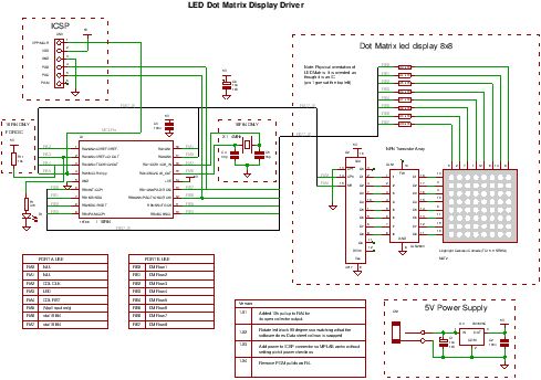
If you wire it yourself you still only need 10 control wires (just wire your leds the same as shown in the module diagram).
For more detail: How to drive a Dot Matrix LED Display.
- How many output pins are normally needed for 64 LEDs?
You would need 64 individual output pins if driving each LED separately. - Can you drive a 64 LED matrix with fewer than 64 outputs?
Yes, you can drive it with only 10 microcontroller outputs using multiplexing. - What principle allows the eye not to notice flicker?
Persistence of vision allows the eye to remember light pulses for about 20ms. - At what frequency must the light be turned on to avoid flicker?
The light should be turned on at a frequency greater than 50Hz. - How is the 64 led display split for multiplexing?
The display is split into 8 rows and 8 columns. - What microcontrollers are suitable for this project?
The project targets the 16F88 or 16F84, which can be retargeted to other PICs with enough pins. - Is special hardware required for the driver circuitry?
No, there are no special notes regarding hardware requirements. - Does the project support displays smaller than 64 LEDs?
Yes, the principle remains the same for displays like a 7x5 matrix with 35 LEDs.
Related projects
PIC16F877 Driving LCD in 4-Bit Mode using PIC16F877 with Proteus Simulation
Introduction This microcontroller project shows how a PIC16F877 can drive an LCD display using 4-bit mode inside a Proteus simulation.The project demonstrates...
Beginner Tutorials · PIC18F4550PICDEM FS USB CDC Evaluation Board using PIC18F4550 with Proteus Simulation
Introduction The PICDEM FS USB CDC Evaluation Board is a practical microcontroller project built around the PIC18F4550, designed to demonstrate USB communication...
Beginner TutorialsPIC12CE518 I2C EEPROM using PIC12CE518 with Proteus Simulation
Introduction This microcontroller project demonstrates how to write and read data using the internal I2C EEPROM of the PIC12CE518 and visualize the...
Beginner TutorialsPico Timer Project using Pico with Proteus Simulation
Introduction Timers are one of the most important features in embedded systems because they allow microcontrollers to perform tasks at precise intervals...
Beginner Tutorials · PIC16F84APIC Stepper Motor Controller using PIC16F84A with Proteus Simulation
Introduction Stepper motors are widely used in embedded systems and DIY electronics projects where precise position control is required. This PIC Stepper...
Beginner TutorialsWhat is a TVS diode? Working principle and parameters of TVS diode
TVS (Transient Voltage Suppressor) diode is a component specially used for protecting circuits. It can absorb excessive voltage pulses in an instant...

Ibrar Ayyub
I am an experienced technical writer holding a Master's degree in computer science from BZU Multan, Pakistan University. With a background spanning various industries, particularly in home automation and engineering, I have honed my skills in crafting clear and concise content. Proficient in leveraging infographics and diagrams, I strive to simplify complex concepts for readers. My strength lies in thorough...