Automatic door locks are becoming popular in industry and many companies and industries are using automatic door locks systems for the safety of their rooms. They are popular in banks. Banks use automatic lock systems to keep security of their money stored in a single room. These automatic door lock systems are also used in hotels,airports prison areas, hospitals and in homes.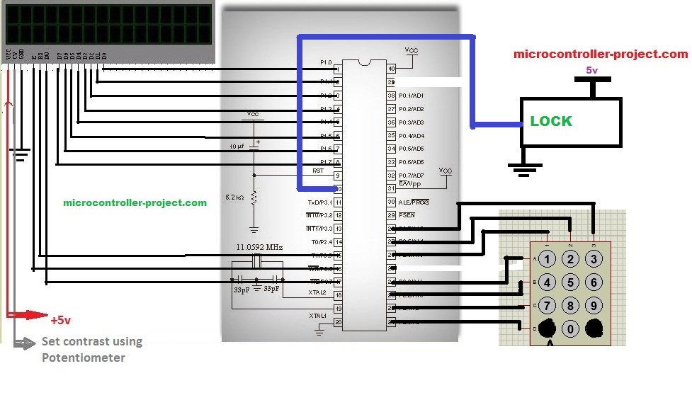
In this project i am designing a same automatic door lock system using 8051(89c51,89c52) microcontroller. The 8051(89c51,89c52) is my intelligent unit that checks whether the password entered is correct or not. Off course you need an intelligent unit that can make decisions on the input by the user. This intelligent unit must be a microcontroller of any type (pic,8051(89c51,89c52),arduino,AVR). But be sure the microcontroller has enough memory to store the code. 16×2 lcd is used to display messages to tell the user whether he entered the right password or not, whether the access to room is granted or not. 4×3 numeric keypad is used to take input from the user. The password consists of numeric data only and no alphabet is used in the password.Other
Project requirements
- 8051(89c51,89c52) microcontroller
- 16×2 lcd
- 4×3 keypad
- Lock
- crystal (11.0592 MHz)
- Bread board(on which circuit is designing)
- reset circuitry(capacitor(10uf) and resistor(8.2Kohm))
- power supply
The lock system is some thing challenging but it is not as much hard to design as it look likes. Below is the circuit that describes the lock system.
The code is simple and easy to understand it is written in c language. First of all the necessary header file reg51.h is included. This header file must be included in every project made using keil as the software tool to write the code. Then the keypad rows and coulombs are declared. 16×2 lcd controlling pins and lock controlling pin is defined. All the upper described pins are declared individually because they are used in our code individually. Data pins for lcd are not defined because whole port1 is dedicated for data pins of lcd, and data is send parallel in 8-bit form.
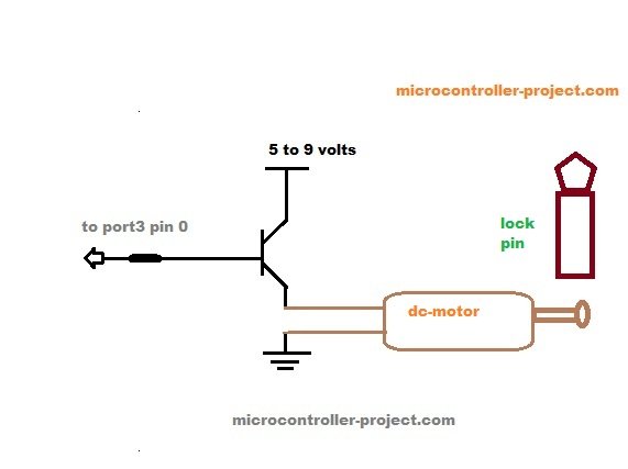
Then some character arrays are defined. These character arrays contains the messages that are displayed on the 16×2 lcd when every certain condition is met or their is some wrong input.The password is manually set in the code it is “1234”. You can change it according to your desire but be sure that the password length should not be greater than 4 characters. The lock controlling pin is also defined as lock at port3 pin 0.various functions and their working
- void delay() Generating variable delay.
- void cmd() Sending commands to 16×2 lcd.
- void lcddata() Sending data to 16×2 lcd.
- void lcdint() Initializes 16×2 lcd.
- char keypad() Scaning keypad keys and taking input from user.
- void main() Main function.
For more detail: Automatic door lock system using 8051(89c51,89c52) microcontroller