Summary of A memory game using a PIC16F84A microcontroller
This article details the implementation of the classic memory game SIMON using a PIC microcontroller (PIC16F84A or PIC16F628). The game uses sequences of tones and matching colored lights, requiring players to repeat increasingly long sequences. The project emphasizes programming complexity, particularly in timing and sequence management. It also discusses the power supply design, favoring a step-up regulator with AA or AAA batteries over a 9V source for longer battery life and regulated 5V output. The step-up regulator uses a fly-back transformer and transistor feedback to maintain stable voltage.
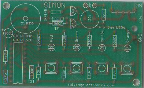
Parts used in the SIMON project:
- PIC16F84A or PIC16F628 microcontroller
- 4 switches
- 4 colored LEDs
- Mini piezo speaker
- Step-up voltage regulator circuit
- Fly-back transformer
- BC338 transistor (driver transistor)
- BC547 transistor (voltage detection transistor)
- Diode (signal diode)
- Capacitor (100µF)
- Resistors (2.2kΩ, 3.9kΩ, 560Ω)
- Battery supply (two AA or AAA cells, or single cell alternative)
This article describes a game we all know. It is SIMON. It uses 4 switches, 4 colored lights and a speaker to produce a sequence of tones and flashes that has to be repeated. After each correct sequence, the computer adds another tone with its corresponding colored LED.
The main purpose for presenting this project is not to deliver a game but to show programming routines.
This program is more complex than you would expect. Most of it is timing and sequences but there are a number of features that have to be studied to to see how they are carried out.
The notes (or tones) are produced by turning the mini-piezo on and off at a definite rate and the length of each note is pre-determined by loading a register with a value.
Each new sequence has to be generated and remembered and all these requirements add up to a lot of programming.
THE PC BOARD
The PC board has been designed to accept either a PIC16F84A or PIC16F628. With the introduction of the’628 to the world market, it has taken over from the PIC16F84A and we will be ceasing to design projects for the ‘F84 and concentrating on the cheaper ‘F628.
The two main improvements with this chip are the lower price and internal 4MHz oscillator (as well as an internal 37kHz oscillator for low-power applications) – a saving of 2 external components. It has three extra in/out lines and many extra files.
THE CIRCUIT
The circuit consists of two parts – the power supply and the microcontroller.
We often put very little thought into the power supply section of a project and expect a battery to do the job perfectly.
It’s not until you connect a battery and watch the voltage droop, that you start to think. That’s what happened with this project.
To start at the beginning:
There are three ways to power this project:
1. A 6v supply with a diode,
2. A 9v battery with a regulator, and
3. A 3v battery with a step-up regulator.
We found the PIC16F628 chip very sensitive to over-voltage and some of the instructions failed to work when we supplied it with a voltage of 5.4v (we used a diode in the Tic Tac Toe project to drop the 6v supply to 5.4v and one instruction did not work when the supply voltage was 5v4). Some chips did not like this arrangement and so we will never use the diode voltage-drop idea again.
When we first designed the Simon project, we included a 5v regulator and connected a 9v transistor-battery.
After less than 1 hour of operation, the 9v was drooping and although the circuit is not critical to under-voltage, we could see the battery would not have a very long life.
So we changed the power supply to a step-up voltage regulator and used two cells to create a 3v supply. The rail-voltage on the chip remained at a constant 5v and the life of two AAA or AA cells was much longer than a 9v battery.
We then placed a “test load” of 100mA on the 5v rail and the voltage dropped only 30mV!
The step-up regulator proved extremely capable and will deliver 5v (actually 4.85v) with a single cell. This means the circuit will operate on 1.5v
The circuit was tested and operated on a single cell until the cell-voltage reached 0.65v The 5v rail was 2.3v The internal resistance of the cells was so high at this “end-stage” that it could only deliver 20mA! This was sufficient to keep the circuit operating!
HOW THE CIRCUIT WORKS
The heart of the step-up regulator section is the “fly-back” transformer – actually a transformer in fly-back mode.
The BC 338 is the driving transistor and is turned on via the 2k2 resistor. This produces magnetic flux in the primary winding that cuts the feedback winding and increases the voltage and current into the base to turn the transistor on MORE. This continues until the transistor is fully turned on.
At this point the magnetic flux in the primary winding is a maximum but it is not EXPANDING FLUX and it ceases to produce a voltage in the feedback winding. The transistor is turned off slightly and the reduced current through the primary allows the flux to start to collapse and produce a voltage in the feedback winding that is in the OPPOSITE DIRECTION. This turns the transistor off more and finally the transistor is fully turned off. The transformer considers the transistor is omitted for the circuit and the collapsing magnetic flux produces a high voltage in the primary winding that this is passed to the signal diode to charge the 100u.
The voltage across the 100u gradually increases and the two “detecting resistors” 3k9 and 560R produce a voltage-divider network with the base of the BC 547 at the “detection-point.”
When the voltage on the base becomes 0.65v, the transistor starts to turn on and effectively puts a resistance between the base and 0v rail of the BC 338. This robs the BC 338 of “turn-on” current and thus it does not turn on as hard.
The output energy from the secondary winding is reduced and the voltage across the 100u does not rise any higher.
For more detail: A memory game using a PIC16F84A microcontroller