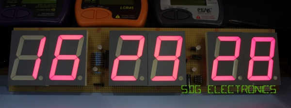
I recently found six 2.3″ red 7 segment displays in my collection which I purchased from Rapid Electronics when they were clearing out non-RoHS stock. Since I have no clock at my work bench I decided to construct one from some prototyping pad board, a Microchip PIC18F26K20 microcontroller and a Dallas DS32KHZ temperature compensated 32.768kHz crystal.
The displays I used are SA23-12SRWA, which don’t appear to be available from Rapid any more, the closest is SA23-12EWA, however, Farnell and the other usual distributors sell them.
 The 7 segment displays are common anode displays, with segments consisting of four red LEDs in series and the decimal places consisting of two red LEDs in series. To reduce the number of GPIO used to drive the display, various methods can be used – such as multiplexing, shift registers or dedicated display drivers. I’ve chosen to use plain display multiplexing, requiring one GPIO for each digit common anode, and one GPIO for each segment – with the colon separators, that gives 7 common anodes, and 8 cathodes with the decimal places and colons commoned together. There are many methods to reduce the number of GPIOs needed further than this, but the chosen microcontroller does not have a shortage of GPIO for this application.
The forward voltage of the segments is slightly high – the datasheet specifies between 7.4V and 10V. For this reason, the anode drivers for the displays have to perform both voltage translation in addition to sourcing enough current for the displays.
A BC327 PNP transistor is used to source the 12V supply to the digit common anode. The transistor used here must be rated for the full current of each digit with all segments lit. The BC327 is rated for a maximum collector current of 800mA, which is more than adequate for these displays, even when driving them at high peak forward currents. With a minimum current gain of greater than 100, the 2kΩ limits the maximum base current to prevent damage to the transistor whilst allowing around 500mA collector current to flow.
The voltage translation is provided by a ULN2003A darlington transistor array. This is effectively a package of 7 open collector darlington transistors which is used in this circuit to turn the BC327 on by pulling the base to 0V through the 2kΩ resistor. The 10kΩ resistor acts as a pull up resistor to hold the transistor off when the open collector transistor is off.
For more detail: 6 Digit LED Clock
