Description
This project is a 2 channel infrared (IR) remote controlled relay driver with power saving. It works with 12-bit SIRC IR signals as used by Sony remote controls.
The controller also features a power save feature which reduces the relay holding voltage to 50% of the relays nominal operating voltage once the relay has switched on.
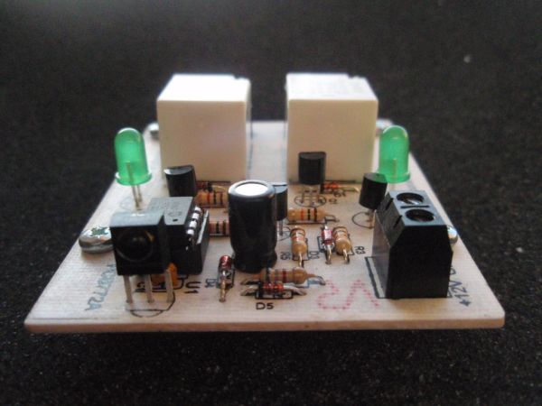
The board uses Microchip’s low cost PIC10F200 microcontroller along with a handful of easy to find components making this possibly the lowest cost remote controlled relay driver around. Everything you need to know to build this project, including the firmware code is right here on the project page.
Don’t forget to check out the accompanying mini IR remote control which can be used with this project.
Circuit Description
The board requires a 12 volt DC supply input. This is fed through diode D5 which provides protection from a reversed connection of the power supply. Capacitor C2 is used for decoupling the supply. The 5 volt supply needed by the microcontroller U1 and the IR receiver U2 is generated using a simple zener shunt regulator comprising R6 and the 5.1 volt Zener diode D4.
The relays are switched on by microcontroller U1 via driver transistors Q1 and Q4. These are low power NPN transistors, in this case BC547 but virtually any small NPN transistor will work here as they only need to switch around 30mA – BC548 or BC549 would also work well. Diodes D1 and D2 provide protection for the transistors against the back EMF voltage transient when the relays are switched off.
The controller also features a power saving control which reduces the power consumption of the relays by around 50% when they are on. Relays of the type used here typically need 75% of their nominal voltage to “pull-in”, once on they will ‘hold’ with a lower voltage. The datasheet for the Omron G5LE for example shows a must release voltage of 10% of rated voltage – for a 12V relay that’s around 1.2V. This circuit uses a holding voltage of around 50% or 6 Volts.
Normally the supply voltage is fed to the relay coils via zener diode D3 which drops 5.1 volts leaving around 6 volts across the relay coil. In parallel with D3 is transistor Q2. When this transistor is switched on, it bypasses D3 and provides the full supply voltage to the relays. This ‘boost’ voltage is switched by the microcontroller with Q2 being switched on via Q3. The firmware in the microcontroller detects when a relay is being turned on and applies the boost for a minimum of around 100mS, again the datasheet for the relays gives typical operate time of 10mS, so the 100mS boost guarantees the relay will pull-in before the voltage is reduced. If you find the relay used doesn’t hold fully swap D3 for a 4.7 volt zener.
LEDs 1 and 2 are connected across the relay coils to give visual indication when the relays are on and can be omitted if not required.
The circuit is controlled by U1, a PIC10F200, the smallest and cheapest PIC available from Microchip. The IR signal is detected and demodulated by U2 a TSOP4838 IR receiver IC. This part was chosen because it has a low supply current requirement – typically around 1.5mA – making it ideal for use with the shunt regulator. The output from the TSOP4838 is active low, when a signal is received the output goes to 0V, when no signal is received it is pulled high by an internal pull-up resistor. The signal is decoded using the firmware programmed into the PIC10F200. This has been written to decode the 12-bit SIRC protocol (see download section)
I recently had an email from someone asking why I used the TSOP4838 38Khz transceiver when the Sony SIRC protocol use a 40KHz carrier. It was a good question and the answer is that I source a lot of my parts from Rapid Electronics and they only stock the TSOP4838. In practice this part will work just fine with a 40Khz IR signal. However, if you can get hold of the TSOP4840 (40KHz variant) by all means use it.
For more information on the SIRC infrared protocol and codes see:
![]() If you don’t want the power save feature, replace D3 with a wire link and omit R2,R3,R5,Q2 and Q3.
If you don’t want the power save feature, replace D3 with a wire link and omit R2,R3,R5,Q2 and Q3.
For more detail: 2-Channel IR Relay Controller for PIC10F200