I originally wrote this for my final year project in 2005. I won’t provide a parts list as certain technology has moved on such as the ease of Arduino for the electronics and solar cells are a lot better and readily available now. Also I was a student at the time and so my budget was extremely limited but even today I am happy with my design.
Many parts of the world suffer from lack of clean water to drink and heat to cook their food and get by from day to day. This instructable is designed to try and provide a cheap means of providing clean water and heat to cook with for a very low price tag.
Hydrogen is very easily made by using electrolysis which can be driven from green technologies such as wind and solar power. Electrolysis will work with stagnant or dirty water to provide Hydrogen and Oxygen gas. This gas mixture is highly combustible and as such makes a great fuel source. The added benefit is that burning hydrogen and oxygen produces 100% pure water.
There are probably lots of flaws with this design and essentially what you are making can be very dangerous if left powered and unattended so please be advised. I’ve since been employed in the embedded industry for over 8 years and have learnt a massive amount so please if you have any questions (about electronics / microcontrollers / Arduino) then let me know. Anyway I hope you enjoy reading my instructable as much as I enjoyed designing and building it. I do intend to dig this project out the loft and take a video of it in action. Yes it’s still working after all this time.
Please read on to find out more….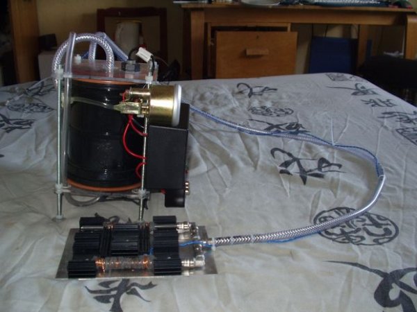
Step 1: Alternative energy and the hydrogen industry
Well researched methods such as solar, wind or water power are fantastic in that they use the energy present in nature and convert that energy into electricity. So ok with these methods we have electricity being produced so now we need a method to use this electricity in our current technology. This is where electrolysis comes into the picture. Electrolysis was discovered in 1800 by an English man named William Nicholson. The reaction that occurs during electrolysis is simple, two electrodes are placed in parallel and submerged in a liquid, the electrodes can be made of stainless steel, aluminum or any other metal as long as it doesn’t react with the liquid and has a high surface conductivity. When an electrical potential is placed between the electrodes in water the only path the current can flow is via the impurities in the water. At the electrodes electrons pass through the water from the cathode to the anode creating concentrations of oxygen and hydrogen at the anode and cathode respectively.
Electrolysis may seem a simple and useless process to use for energy but when used on water a very unique reaction occurs, where there was a hydrogen oxide molecule there becomes two hydrogen molecules and a oxygen molecule (see Fig 2). As both of these new substances are gasses at room temperature they collect into bubbles and rise to the surface of the water as a mixture. This mixture then makes a readily available fuel source that can be used in an engine, cooker, boat, automobile, airplane, heating e.g. all of the products that run on fossil fuels today such as petrol or coal. One drawback to hydrolysis is when using salt water as this produces chlorine gas which is very harmful. This side effect can be easily avoided by removing any salt content through evaporating the water first. In this project tap water will be used as the means of fuel storage so this problem will not apply.
Since the discovery in 1800 and first documentation in 1832 by Michael Faraday, hydrolysis has been used multiple times to try to produce a new form of energy. However none of the products made have ever been very useful due to problems such as lack of efficiency and speed of gas production. Recently though hydrogen technology and electrolysis has come back into the lime light as the fossil fuel industry starts to collapse. Honda’s newest car for example employs a high pressure tank of hydrogen to power in its fuel cells to power the car.
Unfortunately one of the electrolysis researchers called William Rhodes claimed the invention for himself and named the output gas ‘Browns gas’. He claimed to get more energy out of the hydrogen then was put into the water to create it in the first place. This is obviously against the laws of physics and thermodynamics but still he used his rouse to extort a great deal of money, claiming it was for further research. He then disappeared with the money and was never heard from again however his inventions (scams) still live on.
Another Recent development that has helped the start of the hydrogen industry was the fairly new discovery of hydrogen fuel cells (see Fig 3). These are constructed from two chambers to hold hydrogen and oxygen with a PEM (Proton Exchange Membrane or Polymer Electrolyte Membrane) separating the gasses. When hydrogen and oxygen are present on either side of the material a current is generated, water and heat are given off. However there are difficulties with this technology as when the fuel cell is running one side of the PEM tries to dry out and will crack if not kept wet, the other side needs to be dry to conduct the current and is producing water. This makes it difficult to get the fuel cell to work at all or for any sustained period so it will not be included in the project as the budget and technology is limited.
here is however hope for the hydrogen industry in sight, a company in Australia seem to have got it right, producing goods such as water fueled generators, fuel cells, electrolysis chambers, hydrogen boilers etc, proving that if used correctly hydrogen can be a very useful and versatile fuel medium.
With all this information in mind a project was chosen to demonstrate this remarkable technology and the benefits that it would bring to the fuel and power industries. The aim of the project is to make a cooker to demonstrate how simple it is to manufacture the hydrogen and oxygen fuel mixture locally on site and as needed to prevent the need for storing excess. To demonstrate this technique and test its efficiency the project is going to be based on a hydrogen cooker with gas being produced locally in a sealed pressurized chamber. Figure 4 on the left shows this said system with a device between the input gas chamber and the output hob. This device allows combustion to be quenched if it manages to travel up the fuel pipe before it manages to reach the hydrogen production chamber.
(Fig 5) is a picture of the first electrodes that was constructed to test the feasibility of the output gas as a fuel source. The electrodes were made by sanding down a steel can and shaping a steel metal plate around a bottle so it would fit around the can. Wire was then threaded around the can to insulate it from the metal sheet and act as a spacer to keep the distance between the plates constant. Using a 12 volt battery connected to the anode and cathode of my electrodes I submerged the device in tap water and waited for a result. The output was almost immediate and to my surprise the whole surface area of the steel plates was covered in bubbles of gas given off from the process.
To provide power for my hydrogen cooker system it was decided that green energy should be used because if the system was just plugged into the mains then the process would be running mainly on fossil fuels and would defeat the purpose of this clean recyclable energy. The green energy chosen to power the cooker was primarily solar as this is a well established technology and it is generally always light for some time every day (see Fig 7). A second green energy was then included to complement the solar power and help to keep a trickle of charge running to the battery. This was chosen to be wind power as wind is present all day and night and it is also easy to implement with a simple motor and spinner assembly (see Fig 6).
Step 2: Design Concepts
The cooker system will be constructed as shown in Fig 8. It will consist of a solar cell and a wind turbine powering a rechargeable battery through a regulator. The battery will then power a microchip microcontroller connected to a L.C.D screen and the chamber electrodes. The production chamber will also be monitored by the microcontroller by means of water level, hydrogen pressure and temperature sensors. The sensors outputs will be displayed on the L.C.D and hydrogen production will be shut off after a certain pressure (around 5psi) to ensure safety.
(Fig 9) The first chamber made and designed to produce the hydrogen for the project. After construction it was ascertained that although the chamber was water tight and pressure tight, it probably wouldn’t be very hydrogen tight. Therefore another technique was employed to manufacture the production chamber. Instead of trying to make the whole chamber, bought components with seals would be obtained and used instead to guarantee hydrogen would not escape at least short term.
After shopping around looking for the strongest and best sealed container, it was decided to use a heavy duty straight drain pipe connector and two heavy duty drain pipe end caps. These were chosen because they were strong and resilient and also came with a perfect seal ideal for trapping in hydrogen. These drain pipe pieces are to be connected into the designed system by means of using polycarbonate squares to grip the ends of the two caps (see Fig 10). The polycarbonate will then be squeezed together using strips of threaded metal studding. The controller electronics will then be attached to this studding and encapsulated inside a box to prevent any unwanted sparks getting near to the hydrogen.
With the hydrogen and oxygen mix being produced there will have to be measures put in place to ensure the safety of surrounding population. The worst thing that could happen is if a flame or spark got into the production chamber and came into contact with the pressurized gas. Using a fish tank bubbler submerged in a separate water tank (Fig 11), there is no way for a combustion to travel from the hob to the production chamber.
Rather then a propane or butane cooker which needs a large quench gap, primary and secondary air mixing to burn correctly, hydrogen needs a much smaller quench gap to prevent the combustion reaching the inside of the gas pipe. Also unlike propane or butane, hydrogen cannot have primary or secondary air mixing as oxygen is already inside the mixture. As the gas travels though this quench gap there is a maximum amount that can travel though the hole at any time. Therefore the bigger the quench gap is, the more gas that can come through, making it easier for the combustion to travel back through and along the stream of gas. For hydrogen this small quench gap (Approx 1mm) keeps the system from rapidly loosing pressure and also to help prevent the combustion reaction from traveling back past the gap and further up the pipe. (Fig 12) shows a hydrogen burner with steel wool covering the quench gaps in the piping. This steel wool is useful as it firstly reduces the temperature of the burning hydrogen by limiting the surrounding oxygen from reaching the reaction, and secondly useful by acting like a catalyst. Once the gas is ignited the wool will get heated up and then act to combust any further gas as it flows through helping to create a steady output temperature.
Step 3: The Electrodes
Firstly a second experiment was done by using several aluminum plates and separating them with various insulators to vary the width between the plates (see Fig 13). Each time the width of the insulator between electrodes was altered; the electrodes were clamped together, submerged into tap water and a current was applied. Estimated output was decided on disturbance of water, quantity and size of gas bubbles. After testing lots of insulating sizes and recording the findings, the best result was when the plates were around 1mm apart.
Now that a suitable insulating gap had been found more plates were added to maximize conductivity and spacers were glued to each plate in every corner (see Fig 14). The plates were then held together by means of two pieces of strong pieces of elastic. Each plate was tested for connectivity to its wire and that no connection was present to its surrounding plates.
The wires were then cut to size and secured in place by the elastic (see Fig 15). Bits of the plastic insulation from some mains cable was used to separate the places were the cables touch the electrodes to guarantee that none of them would touch their neighbor.
The finished electrodes were then placed in the bottom of the chamber (Heavy duty drain pipe end piece). Pieces of heavy duty plastic were cut into shape and used to wedge the electrodes in place in the chamber bottom. The whole setup was then glued and allowed time to set (see Fig 16). Conductivity between the electrodes was then rechecked for safety reasons.
Step 4: Bubbler Chamber
Shown here is a fish tank bubbler stone attached to a plumbing end piece (see Fig 17). A hole was drilled in the end cap to allow the hose from the bubbler stone to be pushed through and glued in place. Epoxy resin was used to hold the bubbler stone in place and help seal in the hydrogen.
The finished bubbler chamber with bubbler stone sealed inside is now ready to filter the hydrogen output in order to prevent a combustion reaction from ever reaching the hydrogen production chamber (see Fig 18). Hole drilled in another end cap and a stainless steel pipe fitting was glued in place to allow for the incoming hydrogen gas to get out again and be piped to the hob.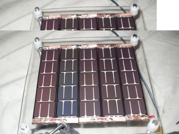
Step 5: Pressure Chamber
With the production chamber partially completed it was time to test the output from the electrodes. The chamber was partially sealed to contain the produced hydrogen and oxygen gas and then a filled with tap water for the chemical reaction to occur. A 12 volt potential from a small lead acid battery was then applied across the anode and cathode of the electrodes. Output gas from the chamber was piped into a container of water and allowed to bubble into an upside down submerged container (see Fig 19). A stop watch was then started to measure how long it took the electrodes to produce 250ml of the hydrogen and oxygen mix. After only 11 minutes of producing gas the 250ml level was reached and the electrodes were then deactivated. The hydrogen and oxygen was then tested for its purity by raising the container up out of the water at the same time as inserting a lit splint into the gas. (Warning… I don’t advise you do this unless you know what your doing!!!). A rather loud ‘pop’ came from the mixture as it combusted proving that there was indeed hydrogen and oxygen present in a substantial enough level to provide power for a device. The bubbler chamber was not needed for this test as currently no hydrogen or oxygen is being held and allowed to build up anywhere to any hazardous (explosive!!!) pressure.
(Fig 20) is the completed hydrogen production chamber with analogue safety pressure gauge attached. This extra gauge is needed to a: verify the digital input pressure and b: act as a backup if the microcontroller fails or hangs. Also shown on the right of the chamber is the release valve used to control the flow of the output hydrogen and oxygen.
For more detail: Gas Cooker & Water Purifier Using Free Energy