Summary of 1Hz Clock Generator using PIC12F675
The article describes a 1Hz Clock Generator using a PIC12F675 microcontroller with a 32.768 kHz crystal oscillator. The PIC's internal clock is divided to 8192 Hz, and Timer1 is configured to overflow every second by setting its initial value to 0xE000. This setup generates a precise 1Hz interrupt, useful for blinking an LED or as a time base for clocks. The project includes MikroC source code to implement the timer interrupt and GPIO control for the output signal.
Parts used in the 1Hz Clock Generator:
- PIC12F675 microcontroller
- 32.768 kHz crystal oscillator
- LED (for blinking output)
- Resistors (for LED current limiting)
- Power supply (e.g., battery or regulated DC source)
- Breadboard or PCB for assembly
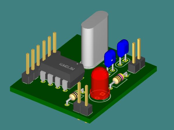
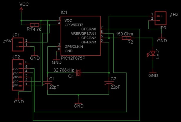
Based on the idea from http://www.josepino.com/pic_projects/?timebaseI have created a 1Hz Clock Generator. I use PIC12F675 as it’s available locally. Its price is just about US$1.

The concept is using 32.768kHz crystal as a clock for the PIC. Therefor, the internal instruction clock is 32768/4 = 8192 Hz. By using the 16 bit Timer1 to count the instruction clock cycles, the interrupt will occur every 8 second. This period can be reduced by setting initial value of the Timer1 (TMR1H:TMR1L). I have to make Timer1 to count up to 8192 for generating overflow interrupt every 1 second. To make Timer1 count up to 8192, the initial value of TMR1 must be 65536-8192 = 57344 or 0xE000. This means TMR1H = 0xE0 and TMR1L = 0x00. In this case, I need to set only the TMR1H=0xE0 and let TMR1L runs continuously. By changing the initial value of Timer1, I can generate almost any frequencies.
An application for this project is a precise 1Hz blinking LED signal 🙂 ha ha. I know that it’s not useful but I think it’s fun to look at (am I crazy?). Another application is a precise 1Hz time base for a clock.

The source code is written in MikroC.
// PIC12F675
// 1Hz Time Base Osc.
// Timer1 Module
// 32.768 KHz
unsigned short tick;
void Init ();
void interrupt ()
{
if (PIR1.TMR1IF)
{
TMR1H = 0xE0;
PIR1.TMR1IF = 0;
tick = 1;
}
}
void main ()
{
tick = 0;
//Initialize Ports and Timer1 Module
Init ();
while (1)
{
if (tick)
{
tick = 0;
GPIO = (1 << 2);
}
if (TMR1H > 0xF0)
{
GPIO = 0;
}
}
}
void Init ()
For more detail: 1Hz Clock Generator using PIC12F675
