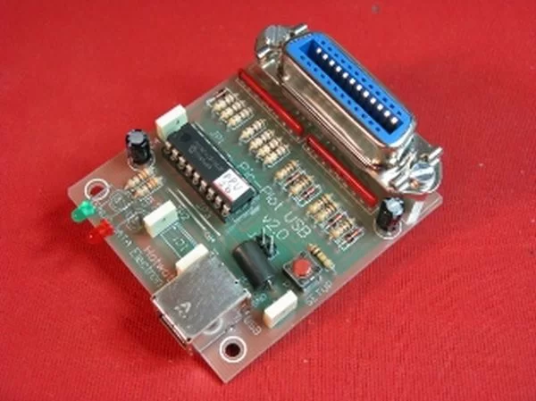
Pic-plot now goes to USB! A perfect low cost solution to quickly get screen plots of your GPIB instrument on your laptop PC without complex software. It emulates the HP7470A operation on the GPIB side, and outputs the HP-GL data at the USB port to be read and stored on the PC by any capturing software. GPIB addresses and other set-and-forget parameters can be configured by a simple Setup menu, then no Dip-switches are used.
Power is taken from the USB port to simplify cabling and get rid of a DC adaptor. The operation of this interface is not just limited to digital plotter emulation: any data intended to be received by a GPIB Device (addressable or listener only) can be captured from the instrument and brought out to the USB port, including raw measurement arrays or rasterized data for a graphic printer. It is based on a PIC16F628 microcontroller and an FT232R chip. PCB size is just 57x64mm.
SCHEMATIC AND DETAILS
SOFTWARE
USE AND OPERATION
VERIFIED GPIB INSTRUMENTS
SCHEMATIC AND DETAILS
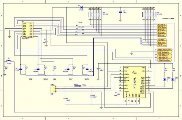
The hardware of Pic-Plot2 interface is quite simple: the active components are a Microchip PIC16F628 microcontroller and an FT232 chip from FTDI. The microcontroller manages the GPIB protocol and signals, while the FT232 does the bridging between the USB and the microcontroller UART. No oscillator crystal is needed because the FT232 provides the 12 MHz clock for the microcontroller, and the 5V needed to supply the whole circuit are taken from the USB host PC.
The microcontroller does all the necessary jobs to emulate GPIB Device functionality, in both Listener and Talker mode, by recognizing addressing, commands and managing the Handshake lines. Controller mode is not needed for the intended functionality, and therefore is not supported. Once the device is addressed and it receives data from the Talker, the same data are forwarded from microcontroller UART to the FT232 at 38400 baud. Then the FT232 manages the USB communication to the host PC where a Virtual COM Port (VCP) has been created by installing the proper drivers. A standard A-B USB cable is needed for data and power connection. There is no power switch: the interface is ON whenever plugged to the host PC.
Two LEDs (LD1-green, LD2-red) respectively indicate:
– Successful bus enumeration
– Data traffic (RX or TX) over USB bus
A small pushbutton switch is provided to enter Setup mode. In this mode the PC is used to read/change a few set-and-forget parameters that are stored in the non-volatile memory of the microcontroller. Even if the GPIB cable can be left connected to the instrument, in Setup mode the GPIB port is not monitored by the Pic-Plot2. Normal operation is restored at the end of Setup procedure, or unplugging-replugging the interface from the host PC. More details about Setup mode can be found in the USE AND OPERATION section.
Herebelow the drawing of the PCB layout and the close-up pictures of a mounted unit:
The FT232R, which is the only SMT component, is mounted at the copper side of the PCB. External connections are the B-type USB female socket and the GPIB female socket. In addition, if the board will be enclosed in a box, the two pin connector in parallel with the Setup pushbutton will come handy to connect a panel mount one. PCB size is 57x64mm.
For more detail: Pic-Plot2 GPIB to USB converter using PIC16F628


