Summary of XBee radio communication between PICs using pic-microcontroller
This article details how to establish wireless communication between PIC microcontrollers using XBee radio modems based on the IEEE 802.15.4 protocol. It explains the hardware setup, including voltage regulation and serial interfacing, and describes software tools like X-CTU for configuration. The guide covers connecting XBee modules directly to UART ports or via RS-232 transceivers for PC interaction, while also providing a comprehensive list of AT commands for configuring baud rates, network channels, and addressing modes.
Parts used in the Wireless PIC Communication Project:
- XBee radio modems
- PIC microcontrollers
- 3.3 voltage regulator
- MAX232/ST232 voltage shifting transceiver chip
- Four external capacitors
- One bypass capacitor
- DE9F 9-pin connector (Digikey part number 209FE-ND)
- X-CTU terminal program software
- USB to RS-232 conversion cable (optional)
Overview
Typically, two pics communicate by RS-232, a wired transmission. However, it may be desirable to communicate via a wireless link. This wiki page demonstrates using XBee radio modems which conform to the IEEE 802.15.4 protocol. These radios will allow for wireless communication between two PICs and between a PIC and a computer.
The IEEE 802.15.4 is a point-point/point-multipoint communications protocol (similar to Bluetooth) designed for low-power devices. Like Bluetooth, the IEEE 802.15.4 specification also uses the 2.4 GHz ISM band. The ZigBee protocol, which deals with mesh networking and routing, is built upon the IEEE 802.15.4 specification.
The XBee radios, made by Digi (formerly Maxstream), are shipped with firmware implementing the IEEE 802.15.4 protocol, but can be loaded with the ZigBee protocol stack, which can be downloaded from the Digi website. Note that ZigBee is still in its infancy and devices from different manufacturers may not be compatible. The range for an XBee Pro indoors is up to 300 feet while line of site, outdoor communication is up to a mile. (XBee Manual)
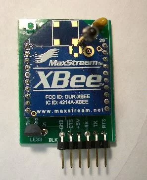
The XBee chip is designed to be mounted in specific sockets (Note: These sockets don’t fit in a standard bread board!) We soldered wires directly to the socket, which were then placed in a breadboard. (Printed circuit boards are being created to fix this issue.) The Xbee also requires a 3.3 voltage regulator.
For the pin locations, see page 7 of XBee Manual or the figure to the right.
For PIC to computer interface, a terminal program such as X-CTU needs to be used. Although other terminal programs might work as well, X-CTU software was designed specifically for the XBee, and in addition to its terminal functions, it also has functions for testing signal strength, reading, saving, and writing the state of the XBee, and updating firmware. The X-CTU program is run on the PC while connected to a X-Bee via a serial port. The X-CTU software can be downloaded from X-CTU Site.
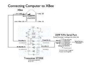
The XBee module can be connected directly to the UART port on the PIC. To connect it to a RS-232 port, one must use a voltage shifting transceiver chip because RS232 signals are from -15V to + 15V. The MAX232/ST232 chip will convert voltage level from RS-232 to TTL logic levels and vice versa. The chip requires 4 external capacitors (the fifth is a bypass capacitor) in order to operate. The transceiver data sheet can be found here.
In the circuit shown above, the serial port uses a DE9F 9-pin connector (Digikey part number 209FE-ND), which is used to connect the computer’s serial port to the circuit.
In order to communicate PIC to PIC, two of the circuits shown on the left should be used.
In order to communicate PIC to computer, one of each of the circuits should be used. A better solution to connecting a PC to an XBee module is to use a cable that connects to the PC’s USB port and converts to RS-232, as described on this PIC RS232 page.
XBee Interface Board
The XBee module can be connected directly to the UART port on the PIC. To connect it to a RS-232 port, one must use a voltage shifting transceiver chip because RS232 signals are from -15V to + 15V. The MAX232/ST232 chip will convert voltage level from RS-232 to TTL logic levels and vice versa. The chip requires 4 external capacitors (the fifth is a bypass capacitor) in order to operate. The transceiver data sheet can be found here.
In the circuit shown above, the serial port uses a DE9F 9-pin connector (Digikey part number 209FE-ND), which is used to connect the computer’s serial port to the circuit.
In order to communicate PIC to PIC, two of the circuits shown on the left should be used.
In order to communicate PIC to computer, one of each of the circuits should be used. A better solution to connecting a PC to an XBee module is to use a cable that connects to the PC’s USB port and converts to RS-232, as described on this PIC RS232 page.
Some commonly used commands:
| Parameter | Description | Command | Value |
|---|---|---|---|
| Basic Commands | Enter command mode | +++ | N/A |
| Exit command mode | ATCN | ||
| Apply changes | ATAC | ||
| Write current parameter values to non-volatile memory (must reset or use ATAC for changes to take effect) | ATWR | ||
| Restore defaults | ATRE | ||
| Reset | ATFR | ||
| For items below, type command followed by a value to set the parameter or without a value to check the current value. | |||
| Baud Rate | Sets the baud rate at which the XBee communicates with the serial device it is physically connected to.
See the XBee manual for information on setting non-standard baud rates |
ATBD | 0-7 (standard baud rates) 0 = 1200 bps 1 = 2400 bps 2 = 4800 bps 3 = 9600 bps 4 = 19200 bps 5 = 38400 bps 6 = 57600 bps 7 = 115200 bps |
| Radio Channel | The XBee can only communicate with other radios using the same channel. | ATCH | Uses 802.15.4 protocol channel numbers. 0x0B – 0x1A (XBee) 0x0C – 0x17 (XBee-PRO) |
| Personal Area Network (PAN) ID | The radio can transmit to a specific network number, or use 0xFFFF to broadcast messages to all PANs | ATID | 16-bit |
| Serial Number | Every radio has a 64-bit, read-only serial number. It can be identified by other radios using this number. | ATSH (high byte) | N/A |
| ATSL (low byte) | N/A | ||
| 16-bit Device ID | You can identify a specific XBee using a 16-bit Device ID instead of the 64-bit serial number. See Destination ID for more information. | ATMY | 16-bit |
| Destination ID | Specify the device ID of a specific XBee to transmit to or use 0x000000000000FFFF to broadcast to the entire PAN.
To use 16-bit addressing, set the high byte to 0 and the low byte to the 16-bit Device ID of the XB you are transmitting to. |
ATDH (high byte) | 16-bit |
| ATDL (low byte) | 16-bit | ||
| API Mode | Gives you more control over communications between XBees, including non-standard packet sizes. Refer to the XBee manual for more information on API/Transparent Mode. | ATAP | 0 = API disabled (use Transparent Mode) 1 = API enabled 2 = API enabled (w/ escaped control characters) |
For more detail: XBee radio communication between PICs
- How do two PICs communicate wirelessly?
Two PICs communicate by using XBee radio modems conforming to the IEEE 802.15.4 protocol instead of wired RS-232. - What protocol does the IEEE 802.15.4 specification use?
The IEEE 802.15.4 specification uses the 2.4 GHz ISM band, similar to Bluetooth. - Does ZigBee work with all XBee devices from different manufacturers?
No, ZigBee is still in its infancy and devices from different manufacturers may not be compatible. - What is the indoor range for an XBee Pro?
The range for an XBee Pro indoors is up to 300 feet. - Which chip converts RS-232 signals to TTL logic levels?
The MAX232/ST232 chip converts voltage levels from RS-232 to TTL logic levels and vice versa. - How many external capacitors does the transceiver chip require?
The transceiver chip requires four external capacitors plus one bypass capacitor to operate. - What command enters command mode on the XBee module?
Type +++ to enter command mode. - How do you set the baud rate using AT commands?
Use the ATBD command followed by a value from 0 to 7 to select standard baud rates. - What happens if you use 0xFFFF for the PAN ID?
Using 0xFFFF allows the radio to broadcast messages to all PANs. - How can you enable API mode on the XBee?
Set the ATAP parameter to 1 to enable API mode.