Summary of WORLD’S SIMPLEST PROGRAM using PIC12F629
Summary: This article describes building a PIC Programmer MkV and a minimal PIC12F629 circuit (LED + resistor). A tiny assembly program uses the watchdog timer (WDT) to repeatedly reset execution every ~18 ms (with prescaler options) so toggling GP4 causes the LED to flash. Changing option_reg bits alters WDT prescaling and flash rate. The project verifies the programmer, chip, LED circuit, and illustrates WDT behavior.
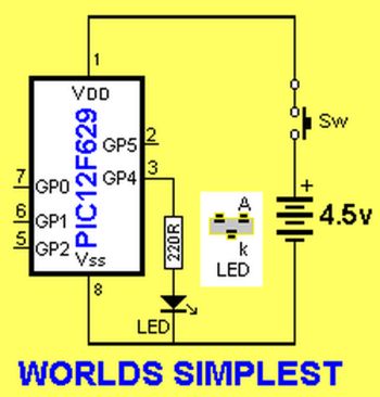
Parts used in the World's Simplest Program:
- PIC12F629 microcontroller
- LED
- Current-limiting resistor for LED
- PC board (prototype or PCB)
- PIC Programmer MkV
- Power supply (suitable for PIC12F629)
- Wires or header pins for connections
This is where you start with programming. Build the PIC Programmer MkV and build the World’s Simplest circuit on a PC board for a PIC12F629 chip, LED and resistor.
When the World’s Simplest Program is “burnt” into the chip, the LED will flash.
This is not a “normal” program as the Watch-Dog Timer has been turned ON and after 18mS it resets the chip to “org 0X00” and the program executes the 8 instructions again.
At the 6th and 7th instruction, the state of GP4 will change from HIGH to LOW or LOW to HIGH and this will toggle the LED.
At the 8th instruction the micro will go to sleep and after about 18,000 microseconds, it will be woken up by the watch-dog timer and go to location 0x00.
At instruction 3, we have added a pre-scaler to the WDT to extend its timing to 18mS x 8 = 0.144Secs. You can change this value and note the different flash-rate.
Making bit 3 of the option_reg = 0 will produce a very fast flash-rate as the prescaler will be removed from the WDT.
This program tests your programmer and the chip you are burning as well as the circuit containing the LED.
It also shows the function of the watch-dog timer.
Normally, when the WDT is turned ON, it must be periodically cleared (reset) via the instruction clrwdt so that it does not come into operation.
For instance, before entering a delay loop, the WDT is reset.
If not, it may reset your program and you will be wondering why your project does not work.
Go to PIC12F629 data and read page 12: OPTION Register. It shows how the bits are allocated to the WDT. Change these bits and see how the flash-rate changes.
Here are the files:
World’sSimplest.asm
World’sSimplest.hex
;*************************************
;WORLDS SIMPLEST PROGRAM             *
;  18-5-2010                         *
;                                    *
;************************************

	list	p=12F629
	radix	dec
	include	"p12f629.inc"

	__CONFIG  _MCLRE_OFF & _CP_OFF &
                _WDT_ON & _INTRC_OSC_NOCLKOUT  ;Internal osc.

;************************************
;Beginning of program
;************************************
	org	0x00
	bsf	status, rp0 	;bank 1
	bcf	TRISIO,4	;GP4 output
	movlw   b'00001011' ;bit3=1=WDT  011=/8 WDT=18mSx8=0.144Sec
        movwf   option_reg     	;must be in bank 1
        bcf	status, rp0	;bank 0
        movlw	b'00010000'	;to toggle GP4
	xorwf	GPIO,f
	sleep

	END
|
Here are some changes you can make to see the differing flash-rates:
change
sleep
to:
goto $
change
movlw b’00001011′
movwf option_reg
to:
movlw b’00001111′
movwf option_reg
or to:
movlw b’00000111′
movwf option_reg
Source : WORLD’S SIMPLEST PROGRAM using PIC12F629
- What does the Worlds Simplest Program do?
It toggles GP4 on the PIC12F629 so an LED flashes by using the watchdog timer to reset and re-execute the 8-instruction loop. - How is the watchdog timer used in this program?
The WDT is enabled so that after its timeout the chip resets to org 0x00, causing the program to run the 8 instructions repeatedly and toggle the LED. - How can I change the LED flash rate?
Modify the option_reg bits that control the WDT prescaler (for example movlw b00001011, b00001111, or b00000111) to change the prescale and flash rate. - What happens at instruction 8 in the program?
The program executes sleep, and the WDT wakes the micro after about 18,000 microseconds (or longer with prescaler) causing a reset to 0x00. - Why might my program reset unexpectedly when using WDT?
If the WDT is enabled and not periodically cleared with clrwdt before delays, it will reset the program and appear as unexpected resets. - Which register and bit control the WDT prescaler in this example?
The option_reg holds the prescaler and WDT settings; changing bit 3 of option_reg affects prescaler removal and flash rate. - What does making bit 3 of option_reg equal 0 do?
Setting bit 3 to 0 removes the prescaler from the WDT and produces a very fast flash rate. - What files are provided with the article?
WorldsSimplest.asm and WorldsSimplest.hex are provided.