Summary of Wireless Doorbell Receiver
This article details the construction of a wireless doorbell receiver, the second part of a two-part project. Upon receiving a valid signal from a transmitter, the device triggers an 8-bit "ding-dong" sound and blinks an LED five times. The circuit is primarily powered by 230V AC mains converted to 5V DC, though it can operate on AA batteries. The system relies on a PIC12F617 microcontroller running at 8 MHz with JAL software to decode RF messages and control audio and visual outputs.
Parts used in the Wireless Doorbell Receiver:
- Breadboard
- PIC microcontroller 12F617
- Electrolytic capacitor 47uF/16V
- Ceramic capacitors (2 * 100nF, 1 * 680 nF)
- 433 MHz ASK RF Receiver
- Resistors (1 * 33k, 2 * 1k, 2 * 220 Ohm)
- Diodes (2 * 1N4148)
- Transistors (BC639, BC640)
- LEDs (1 Red, 1 Amber)
- Loudspeaker 8 Ohm
- Plastic housing
- 5 Volt power supply
- Fuse holder + fuse 100mA Slow
- Switch
This project describes the second part of the following two projects:
- A wireless doorbell transmitter as described in the Wireless Doorbell Transmitter Instructable. This Instructable also gives some introduction to these projects.
- A wireless doorbell receiver described in this Instructable.
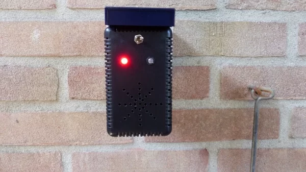
The wireless doorbell receiver will make a sound and will blink a LED 5 times after it has received a valid message from the wireless doorbell transmitter. The sound produced by this receiver sounds like ding-dong although but you can call it ‘8-bit audio’ because of its simplicity.
The device is powered by the 230 Volt AC mains using a 5 Volt step down converter that generates the 5 Volt DC voltage. Although it could have been designed to work on a battery, I did not need that. It should be possible to power it with three 1.5 AA batteries since both the receiver and the microcontroller should work well on 4.5 Volt or even 3.6 Volt in case of rechargeable batteries.
Also here I built this project around my favorite micro controller the PIC but you can also use an Arduino.
Step 1: Required Components
You need tohave the following components for this project:
- A piece of breadboard
- PIC microcontroller 12F617, see win-source
- Electrolytic capacitor 47uF/16V
- Ceramic capacitors: 2 * 100nF, 1 * 680 nF
- 433 MHz ASK RF Receiver
- Resistors: 1 * 33k, 2 * 1k, 2 * 220 Ohm
- 2 * diode 1N4148, see win-source
- Transistors: BC639, BC640
- LEDs: 1 Red, 1 Amber
- 1 loudspeaker 8 Ohm
- A plastic housing
- For mains power (not shown on the schematic diagram):
- 5 Volt power supply
- Fuse holder + fuse 100mA Slow
- Switch
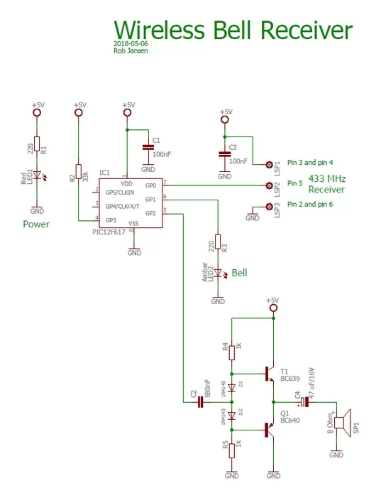
See the schematic diagram on how to connect the components.
Step 2: Designing and Bulding the Electronics
All control is performed by the PIC12F617 in software. As mentioned earlier I designed this project so that it is powered by the mains using a step down converter. In this case be very careful not to touch the 230 V!
A simple amplifier is used to drive the 8 Ohm loudspeaker.
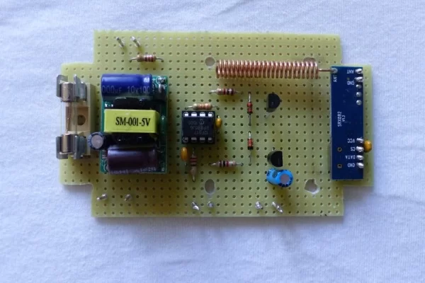
Building the circuit can easily be done on a small breadboard with suitable housing. In the pictures you can see the circuit as I built it on the breadboard including the final result when put in a plastic housing. This housing has a connector that can be directly plugged into the mains.
Step 3: The Sofware and Final Operation
As already mentioned, the software is written for a PIC12F617. It is written in JAL. In this project the PIC runs on an internal clock frequency of 8 MHz.
The software does the following:
- Decode the received message via the RF link. Since the wireless doorbell transmitter will repeat the same message 3 times, the receiver will only use one of the messages by checking the sequence number of the message. Timer 2 is used by the Virtual Library to decode the received RF messages with a bit rate of 1000 bits/s.
- When a valid message is received, generate a ding-dong sound with the frequencies 1667 Hz and 1111 Hz and blink the LED 5 times. Timer 1 is used to generate the ding-dong sound.
In the video you can see and hear the wireless doorbell receiver in action.
The JAL source file and the Intel Hex file are attached. If you are interested in using the PIC microcontroller with JAL – a Pascal like programming language – please visit the JAL download site
Have fun building your own project and looking forward to your reactions.
Attachments
Source: Wireless Doorbell Receiver
- What happens when the receiver gets a valid message?
The device produces a ding-dong sound and blinks an LED 5 times. - Can this project be powered by batteries instead of mains?
Yes, it can work with three 1.5 AA batteries providing 4.5 Volts or rechargeable batteries at 3.6 Volts. - Which microcontroller is used in this project?
The project uses a PIC12F617, though an Arduino could also be used. - How does the software handle repeated messages?
The software checks the sequence number and only processes one of the three repeated messages sent by the transmitter. - What frequency does the PIC run at in this design?
The PIC runs on an internal clock frequency of 8 MHz. - What programming language was used for the software?
The software was written in JAL, which is described as a Pascal-like programming language. - How are the ding-dong sounds generated?
Timer 1 is used to generate the sound using frequencies of 1667 Hz and 1111 Hz. - What type of RF receiver is required?
A 433 MHz ASK RF Receiver is needed to decode the incoming signals.