
Summary of VXO — based PLL Frequency Synthesizer for 7 MHz
This article details a VXO-based frequency synthesizer project covering 6.99 to 7.103 MHz using stock components. The design utilizes a 21.4773 MHz crystal divided by three, combined with inductance for stability, and employs a BD139 transistor, an AND gate inverter, a low-pass filter, and an NE612 mixer.
Parts used in the VXO-based Synthesizer:
- 21.4773 MHz crystals
- Series inductance
- BD139 transistor
- AND gate
- Low-pass filter
- NE612 mixer
- Phase Frequency detector
- CMOS clock (1 MHz)
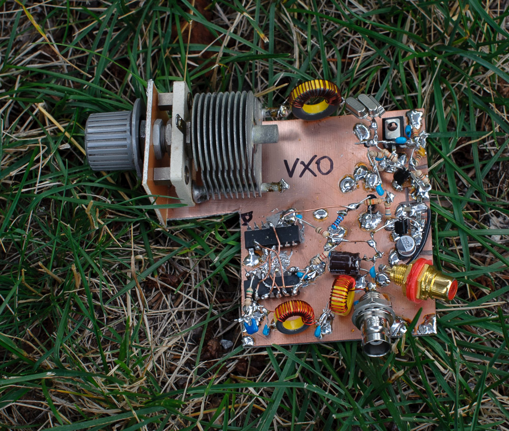
In EMRFD, 4.10, Wes provides the schema for a versatile VXO – extending frequency synthesizer. Although, I referred him to Wes for help, a reader asked me some questions and I ended up designing some pieces for him. In order to test some of my ideas, I made a VXO – based synthesizer that tuned from 6.99 to 7.103 MHz using only parts I had in stock.
Above — Output of the 1 MHz CMOS clock applied as the reference oscillator. Initially, I planned to divide a 2 MHz crystal oscillator in half with a flip-flop circuit, but remembered that someone sent me some high-grade 1 MHz clocks a few years ago.
To make a VXO to mix with a ~7 MHz VCO, you’ll need a crystal that is higher in frequency than the highest frequency you want to synthesize. Some rummaging revealed a bag of 21.4773 MHz crystals that I could divide by 3 to garner 7.159 MHz.
To afford a reasonable delta F, three were placed in the super VXO fashion and I applied the smallest amount of series inductance that would ensure a reasonable delta F with solid frequency stability.
Above — The schematic of my VXO. Through experiments I determined that 3 crystals and the inductance shown gave a stable ~30 KHz swing in frequency when divided by 3. A BD139 with low flicker noise gets buffered, digitized and then buffered again by a single inverter crafted by an AND gate.
The simple divide by 3 circuit lacks a 50% duty cycle, but worked OK. A low cutoff frequency low-pass filter serves to clean up the waveform, plus attenuate the output signal so that it is somewhere between 200 and 300 mV peak to peak to chop the NE612 mixer without excessive distortion in the mixer output.
Dividing by 3 drops the raw VXO range by 1/3, the phase noise by ~ 9.5 dB and also reduces frequency drift even further.
Above — The output of offset mixer stage just at the collector of the final transistor used to digitize and feed the Phase Frequency detector [ ~ 100 KHz offset ]. I first tested it with a 7 MHz bench signal generator offset from the VXO by ~143 KHz to 58 KHz.
For More Details : VXO — based PLL Frequency Synthesizer for 7 MHz
- What frequency range does this VXO-based synthesizer cover?
The synthesizer tunes from 6.99 to 7.103 MHz. - How was the reference oscillator frequency selected?
A 1 MHz CMOS clock was used instead of dividing a 2 MHz crystal oscillator. - Why were three crystals placed in the super VXO fashion?
This configuration was used to afford a reasonable delta F while ensuring solid frequency stability. - Does the divide by 3 circuit provide a 50% duty cycle?
No, the simple divide by 3 circuit lacks a 50% duty cycle but worked okay. - What is the purpose of the low cutoff frequency low-pass filter?
The filter cleans up the waveform and attenuates the output signal to between 200 and 300 mV peak to peak. - How does dividing by 3 affect phase noise?
Dividing by 3 reduces the phase noise by approximately 9.5 dB. - What offset frequency was used when testing with a bench signal generator?
The initial test used a 7 MHz bench signal generator offset from the VXO by approximately 143 KHz to 58 KHz. - Which component is used to chop the NE612 mixer without excessive distortion?
The signal is conditioned to be between 200 and 300 mV peak to peak to chop the NE612 mixer.

