
Summary of Visualizing comparator and Op Amp hysteresis
Hysteresis improves comparator stability with noisy inputs by creating different thresholds for rising and falling signals. This article describes measuring hysteresis by plotting input vs output on an oscilloscope while sweeping input voltage. Resistors R1 (potentiometer) and R3 set trip voltage and hysteresis; R2 provides a crude reference at the inverting input; R4 is a pull-up for open-collector outputs. A breadboard setup holding reference at 1.72 V and fixed wiper positions is used to compare hysteresis across different comparators and op amps, noting that hysteresis varies with device-specific characteristics.
Parts used in the Hysteresis Visualization Project:
- Comparator or Op Amp devices (various common models)
- R1 potentiometer (sets trip voltage and hysteresis)
- R2 potentiometer (crude voltage reference for inverting input)
- R3 fixed resistor (works with R1 to determine trip voltage and hysteresis)
- R4 pull-up resistor (for open-collector comparator outputs)
- Breadboard
- Oscilloscope (for plotting input vs output)
- Signal source to sweep input voltage
- Power supply for comparators/op amps
Hysteresis can be added to a comparator circuit to improve its stability, especially when the input signal is noisy. In this post, we will examine the hysteresis characteristics of some common comparator and Op Amps using an oscilloscope.
Perhaps the most intuitive way to visualize the hysteresis in a circuit is to plot the input signal (x axis) against the output signal (y axis). So, if we sweep the input voltage we should be able to see the characteristics of the transitioning of the output voltage due to hysteresis.
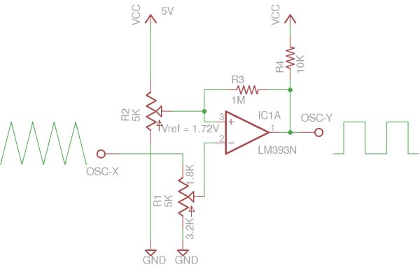
R1 (potentiometer) and R3 determine the trip voltage and hysteresis. Potentiometer R2 serves as a crude voltage reference and sets the reference voltage at the inverting input. R4 is a pull up resistor for comparators with open-collector outputs.
Here is a picture of the setup on breadboard. The potentiometer on the left (which corresponds to R1) sets the reference voltage at 1.72V. This value is used for all the tests conducted below. The actual voltage set for the reference is not very important however, it was mainly chosen for easy visualization and comparison purpose. The potentiometer (R1) connected to the negative input was adjusted to be 1.8K and 3.2K (from input to wiper, and wiper to ground). Again, the wiper position is fixed for all the tests.
Because a comparator’s hysteresis depends on many different factors such as the output voltage swing and input bias current, etc., you will see from the pictures below that even with the other settings unchanged (i.e. same resistor values), the hysteresis changes significantly depending on the comparator/op amps used. So to calculate hysteresis accurately, the characteristics of the comparator/op amp must be precisely known.
For more detail: Visualizing comparator and Op Amp hysteresis
- How is hysteresis visualized in this project?
By plotting input voltage on the x axis and output voltage on the y axis on an oscilloscope while sweeping the input. - Which components determine trip voltage and hysteresis?
R1 (potentiometer) and R3 determine the trip voltage and hysteresis. - What is the role of R2 in the circuit?
R2 serves as a crude voltage reference and sets the reference voltage at the inverting input. - Why is R4 used in some comparator circuits?
R4 is a pull-up resistor used for comparators with open-collector outputs. - Does the reference voltage value critically affect the tests?
No, the reference was set to 1.72 V for visualization; the exact value is not very important for the tests. - Are resistor wiper positions changed between tests?
No, the wiper position is fixed for all tests; R1 was adjusted to specific resistances to set the wiper position. - Will hysteresis be identical across different comparators and op amps with the same resistor values?
No, hysteresis changes significantly depending on the comparator or op amp used, even with the same resistor values. - What device characteristics affect hysteresis measurements?
Output voltage swing and input bias current, among other device-specific characteristics, affect hysteresis.
