A four digit seven segment display. |
The image above shows a four digit seven segment display. These type of displays are widely used to present numerical data to users. Example includes clocks, panel meters, microwave ovens, refrigerators etc. As you can see in a four digit displays there are a total of 4 x 7 = 28 segments (made of leds) so you may think that they will require lots of i/o pins of MCU. But in reality a small trick can greatly reduce the number of i/o pins required.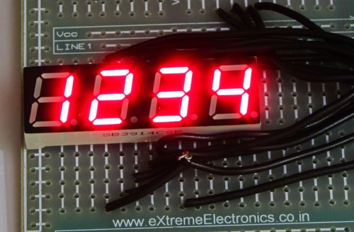
The trick is to activate only one digit at a time. All the segments of each four digit are connected in parallel and common of each four digit is tried to MCUs i/o port via transistors. That means MCU can select any digit and put the segment data which drives the segments. Only the selected digit will light up. Then next digit is selected and segment data is changed according to the digit that must be shown in that place. Similarly each digit is selected and shown. This is done fast enough that the human I cannot see the movement. We can see all four digit lit at the same time as shown in the figure above.
Multiplexed Seven Segment wiring |
To display any four digit number, say 1234 on the display. The following steps are taken.
First the display 1 is select by making SEL1 line high (keeping all other SELx line low), now any segment data sent from MCU will be visible only on DISP1. Now we send the segment data for ’4′, thus it is shown on the DIGIT1.
After some time we select digit 2 by setting SEL2 line high (keeping all other SELx line low) and sending segment data that shows ’3′ on display. ’3′ is shown on DIGIT2
After some time we select digit 3 by setting SEL3 line high (keeping all other SELx line low) and sending segment data that shows ’2′ on display. ’2′ is shown on DIGIT3
After some time we select digit 4 by setting SEL4 line high (keeping all other SELx line low) and sending segment data that shows ’1′ on display. ’1′ is shown on DIGIT2
we repeat the above steps. And we do so fast enough that human eye cannot catch the trick and see all four digits lit at the same time.
Implementing it using PIC MCU
We will use PIC18 series MCU to implement the above technique. To make the refreshing of display automatic we will use TIMER0 module. We set it to interrupt on overflow. If you are new to TIMERs and PIC Interrupt handling please see the following tutorials.
Timer Interrupt Service Routine(ISR) is automatically called by the hardware at specified interval. This ISR switch to next display and changes the segment data according to the digit to be show on that display. If it is on last display it switch back to display number 1. The data that is shown in the display is store in an array named digits[4]. You can modify the digits[] to change the display. For example if you want to display “1234” you need to do the following :-
For more detail: Using Multiplexed 7 Segment Displays – PIC Microcontroller Tutorial