


This was a fun little project I put together in a few
hours for a homemade-themed gift exchange this
Christmas. I had on-hand a "Full Color LED" from
Radio Shack (part 276-0028) which caught my eye
on my last visit there.
The LED has a common anode and three
cathodes, one for each of the three primary colors:
red, blue and green. By changing the duty cycle
(the fraction of time the pin is low) on each of the
three pins controlling the colors, I could create any
color.
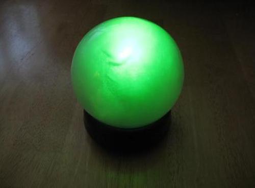
The next step was the housing. I found a good
candidate in a prize I had won for judging a technical
paper competition at Georgia Tech years ago. It was
a sphere with a golf ball inside that you had to move
around until it balanced on a tee. The sphere was a
good size and the polystyrene base made for an easy
mounting of the components.
My first thought for controlling the colors was a simple algorithm
that I think is called "the drunk's walk" - for each step, choose
randomly which direction the step will be (one color a little
brighter, another a little dimmer). The problem with this is that
you're unlikely to get far; you'll likely keep drifting around
wherever you start. The chances of wandering all the way to a
vibrant color were small and I certainly didn't want this thing just
showing different shades of off-white!
Instead I devised a configuration of 10 nodes: three of them
pure colors, seven of them intermediates. The globe would
start randomly on one of these nodes. Every three seconds an
adjacent node would be randomly chosen and the color would
slowly shift to that one over the course of 20 steps.
Here is a graphical representation of the ten nodes showing
(roughly) their colors. The numbers show proportions of red,
blue and green respectively.
The result is a random walk that gets to the more vibrant
colors reasonably often. To be really nit-picky, I don't use all
of the colors that could be generated, only those along the
defined paths.
The circuit is quite simple - a battery, a 5V regulator, a PIC
16F688 microcontroller, and three 470-Ohm resistors from
the LED to the control pins. I later replaced the battery with a
plug consisting of a "wall wart" transformer and a 9V clip.
For more detail: Color Globe using PIC16F688 Microcontroller
Related projects
Determine capacitance by measuring the charging time using PIC16F688
When TEST botton is pressed, RA3 pin is set to "1". R2 and R3 are divide the voltage to 1/2 Vra3 which...
Meters & Test Instruments · PIC16F688Digital Oscilloscope using PIC16F688
Far and away my most ambitious project to date, this digital oscilloscope can sample up to four channels at a rate up...
Sensors & Temperature · PIC16F688Digital Thermometer Using PIC16F688 microcontroller
Digital thermometers are cool devices as they show temperatures in human readable formats. This digital thermometer project is based on a PIC16F688...
Home Automation & SecurityVoice Activated Power Sockets (Home Automation)
Yet another voice controlled home automation system! As shown in the picture, the system can control any electrical appliance, by turning ON...
Home Automation & SecurityHome Security System with GSM Using 8051 Microcontroller
Security is a big challenge everywhere because thefts are increasing day by day owing to the unsafe and insecure security systems in...
Home Automation & SecurityHome Automation and Security System using Microcontroller ATMEGA8 with Arduino Programming
Home automation and security systems have become very popular these days, today industrial automation techniques are widely adopted by luxurious homes and...

Ibrar Ayyub
I am an experienced technical writer holding a Master's degree in computer science from BZU Multan, Pakistan University. With a background spanning various industries, particularly in home automation and engineering, I have honed my skills in crafting clear and concise content. Proficient in leveraging infographics and diagrams, I strive to simplify complex concepts for readers. My strength lies in thorough...