
Summary of Using Fixed Voltage Reference (FVR) for A/D conversion in enhanced mid-range PIC microcontrollers
The article explains using the PIC16F1827 Fixed Voltage Reference (FVR) to provide a stable internal 2.048 V reference for ADC measurements. It describes configuring the FVRCON register to enable 2x gain, selecting FVR as ADC positive reference via ADCON1, and using an LM34DZ temperature sensor as the analog input. The LM34 outputs 10 mV/°F; the PIC converts this voltage and displays temperature on a 2×8 LCD.
Parts used in the Using Fixed Voltage Reference for A/D conversion in PIC16F1827 project:
- PIC16F1827 microcontroller
- LM34DZ temperature sensor
- 2×8 character LCD
- Power supply (VDD, VSS)
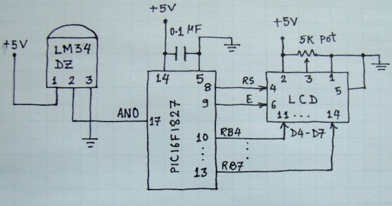
- Connections/wiring between sensor, PIC ADC pin, and LCD
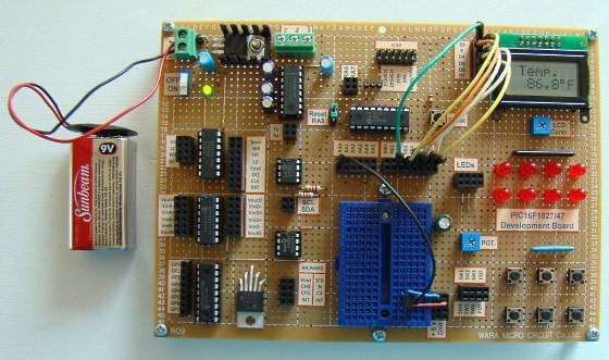 It is called Fixed Voltage Reference (FVR) where the output is very stable and independent of the supply voltage (VDD). The output of the FVR can be configured to supply a reference voltage for A/D conversion internally. This article describes how to configure the FVR module to derive the reference voltage of 2.048 V for A/D conversion in PIC16F1827 microcontroller. The analog signal for this experiment is taken from the output of a LM34DZ temperature sensor. After the A/D conversion, the PIC16F1827 displays the temperature on a 2×8 character LCD.
Theory
LM34DZ temperature sensor
PIC16F1827 is a member of Microchip’s enhanced mid-range 8-bit microcontroller family. It is pin-compatible with the popular 18-pin predecessors such as PIC16F628A and PIC16F88, but is equipped with lot more peripherals and other features. The Fixed Voltage Reference (FVR) module in PIC16F1827 generates a stable voltage reference internally. The FVR output provides three software selectable voltage levels, 1.024V, 2.048V and 4.096V. The output can be configured to supply a reference voltage to the following:
 The actual generated reference voltage is 1.024 V, but with the help of programmable gain amplifiers, it can be amplified by 1x (1.024 V), 2x (2.048 V), or 4x (4.096 V), to produce the three possible voltage levels. The FVRCON register (shown below) is used to configure the settings for the fixed voltage reference. The bit values of FVRCON register to generate 2.048 V as the positive voltage reference for A/D conversion are shown in blue color font.
Once the FVRCON register is configured, the choice of reference voltage for A/D conversion is made through ADCON1 control register. By setting ADPREF<1:0> bits to ’1′, the positive reference voltage for A/D conversion is derived from the internal FVR module. Clearing the ADNREF bit connects the A/D negative reference voltage pin to the ground (VSS).
- What is the role of the reference voltage in A/D conversion?
It determines the ADC range, resolution (Volt/Count), and conversion accuracy based on its stability. - Can PIC16F1827 generate a stable internal reference for ADC?
Yes, it has a Fixed Voltage Reference module that generates stable internal reference voltages. - What voltage levels can the FVR module produce?
The FVR provides selectable outputs of 1.024 V, 2.048 V, and 4.096 V using programmable gain. - How is 2.048 V selected as the ADC positive reference?
Configure FVRCON for 2x gain to produce 2.048 V, then set ADPREF bits in ADCON1 to select the FVR as ADC positive reference. - How is the ADC negative reference connected?
Clearing the ADNREF bit connects the ADC negative reference to ground (VSS). - What sensor is used for the analog input in the example?
The LM34DZ temperature sensor is used as the analog input. - What is the LM34DZ output characteristic?
LM34DZ outputs 10 mV per degree Fahrenheit, so 75°F yields 750 mV. - Can the LM34DZ measure below 0°F in this experiment?
No, because no negative voltage source is used, the LM34DZ cannot measure temperatures below 0°F here. - How are measured temperatures displayed?
The PIC16F1827 displays the temperature on a 2×8 character LCD after ADC conversion.
