Summary of Use an LM317 as 0 to 3V adjustable regulator
Most engineers face the LM317’s 1.25V internal reference limit when needing outputs below that. The article explains an inexpensive 0–3V adjustable regulator that creates a negative bias using a temperature-stabilized constant-current source (D1, Q1, R5, R6) to force R3 to about −1.25V, allowing the LM317 to regulate down to 0V. Zero adjustment is via R6; output is set by R2 and R1 using VOUT = VREF(1+R2/R1) − VR3 (with VR3 ≈ VREF to simplify to VOUT = VREF·R2/R1). The circuit is suitable as a 1.56V battery equivalent for development.
Parts used in the 0 to 3V adjustable regulator:
- LM317 (adjustable three-terminal regulator) IC1
- Transistor Q1 (NPN for constant-current source)
- Diode D1 (used for forward voltage and optional indicator, e.g., 1N4001)
- Resistor R1 (reference divider)
- Resistor R2 (output-setting resistor, example 1.2 kΩ)
- Resistor R3 (compensating resistor biased to about −1.25V)
- Resistor R5 (protects Q1)
- Resistor R6 (adjusts constant-current source and zero adjustment)
Most engineers know that they can use an inexpensive, three-terminal adjustable regulator, such as Fairchild Semiconductor’s LM317, as an adjustable regulator to only some necessary value of voltage, such as 36 or 3V. This value cannot be less than 1.25V without employing other approaches, however. The devices’ inner reference voltage is 1.25V, and their output voltage accordingly cannot be less than this value without potential bias (Reference 1). One way to solve this problem is to use a reference-voltage source based on two diodes (Reference 2). Although this approach is suitable for a 1.2 to 15V or higher-voltage regulator, it is not appropriate for an extra-low-voltage fixed- or adjustable-voltage regulator. The two 1N4001 diodes it employs do not provide the needed potential bias of 1.2V, and they have additional temperature instability of approximately 2.5 mV/K (Reference 3). Hence, additional temperature drifting of the output voltage is approximately 100 mV; it is more than 6% for a 1.5V output voltage and 10% for a 1V output voltage if you adjust the temperature to 20°C—a typical indoor situation. You can solve these problems by using a Fairchild Semiconductor LM185 or an Analog Devices AD589 adjustable-voltage-reference IC. These devices are expensive, however, and, in this case, they require not only additional zero adjustment but also matching. These adjustments at their reference voltages are 1.215 to 1.255V and 1.2 to 1.25V for the LM185 and AD589, respectively. Note that the reference voltage of the LM317 is 1.2 to 1.3V.
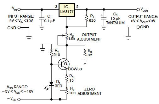
Figure 1 This circuit is an inexpensive approach using a simple 0 to 3V adjustable regulator.
Figure 1 shows an inexpensive approach using a simple 0 to 3V adjustable regulator. You implement the necessary potential bias using a simple temperature-stabilized constant-current source (Reference 4). You calculate this current source using the following equation: I=(VF–VEBO)/(R5+R6), where VF is D1’s forward voltage of approximately 2V and VEBO is Q1’s emitter-base voltage of approximately 0.68V. The current is approximately 1.32/(R5+R6). The constant-current source creates a bias voltage of approximately –1.25V on resistor R3. You implement the zero adjustment using resistor R6, which can change the current of the constant-current source. Resistor R5 protects transistor Q1. You can use D1 as a light indicator. You can adjust the output voltage using resistor R2. Calculate the output voltage as follows: VOUT=VREF(1+R2/R1)–VR3, where VREF is the reference voltage of IC1 and VR3 is some compensative voltage of resistor R3. You should establish this voltage to equal the reference voltage for its compensation. In this case, VOUT=VREF(R2/R1). With R2 having a value of 1.2 kΩ,this circuit found use as the equivalent of a typical battery with an output voltage of 1.56V for development projects.
For more detail:Use an LM317 as 0 to 3V adjustable regulator
- How does this circuit allow the LM317 to regulate below its 1.25V reference?
By creating a temperature-stabilized negative bias on R3 of about −1.25V using a constant-current source, effectively shifting the output range down so the LM317 can produce voltages down to 0V. - What creates the constant current in the bias circuit?
The constant current is produced by D1 and Q1 with resistors R5 and R6 forming a temperature-stabilized constant-current source. - How is the constant-current value calculated?
Using I = (VF − VEBO) / (R5 + R6), where VF is D1 forward voltage (~2V) and VEBO is Q1 emitter-base voltage (~0.68V). - What is the role of R6 in the circuit?
R6 provides zero adjustment by changing the current of the constant-current source. - Why is R5 included in the bias network?
R5 protects transistor Q1. - How is the output voltage calculated?
VOUT = VREF(1 + R2/R1) − VR3; if VR3 equals VREF for compensation, then VOUT = VREF · (R2/R1). - Can D1 be used as an indicator?
Yes, D1 can also serve as a light indicator. - What example output was demonstrated with R2 = 1.2 kΩ?
The circuit produced an equivalent typical battery output of 1.56V for development projects.