


Summary of Unipolar Stepper Motor Control From IR Remote Control Using PIC18F4550
This project demonstrates controlling a 5V unipolar stepper motor's speed and direction using an IR remote with the NEC protocol and a PIC18F4550 microcontroller. The system utilizes external interrupts to decode signals and Timer1 for timing, driving the motor via a ULN2003 or L293D driver while relying on the microcontroller's internal 8MHz oscillator.Parts used in Remote controlled unipolar stepper motor:
- 5V unipolar stepper motor
- PIC18F4550 microcontroller
- IR remote control (NEC protocol)
- ULN2003 or L293D motor driver
- CCS C compiler
This project shows how to control a 5V unipolar stepper motor from IR remote control uses NEC protocol with PIC18F4550 microcontroller. This controller controls the stepper motor speed and direction of rotation.
If you want to see how to drive the unipolar stepper motor using PIC18F4550 microcontroller read the following topic: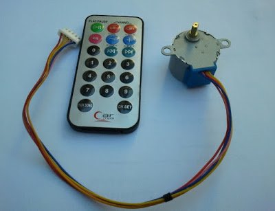 Interfacing unipolar stepper motor with PIC18F4550 microcontroller
And if you want to see how to decode IR remote control with NEC protocol see the following topic:
Extended NEC IR remote control decoder with PIC18F4550 microcontroller
To drive the unipolar stepper motor we need ULN2003 (ULN2004) Darlington transistor array or L293D motor driver as described in the previous topic.
The IR remote control used in this project is shown below: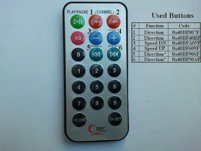 PIC18F4550 microcontroller internal oscillator is used.
Remote controlled unipolar stepper motor using PIC18F4550 CCS C code:
External interrupt is used to read IR remote control signals.
Remote controlled unipolar stepper motor using PIC18F4550 CCS C code:
External interrupt is used to read IR remote control signals.
// Remote controlled stepper motor using PIC18F4550 CCS C code
// http://ccspicc.blogspot.com/
// [email protected]

#include <18F4550.h>
#fuses NOMCLR INTRC_IO
#use delay(clock = 8000000)
#use fast_io(B)
#use fast_io(D)

short Direction;
unsigned int8 step_number = 0, speed_delay = 2;
unsigned int32 remote_code;
#INT_TIMER1                                  // Timer1 interrupt ISR
void timer1_isr(void){
  remote_code = 0;
  clear_interrupt(INT_TIMER1);
  disable_interrupts(INT_TIMER1);
}
#INT_EXT                                     // External interrupt ISR
void ext_isr(void){
  unsigned int8 count = 0, i;
  unsigned int32 ir_code;
  // Check 9ms pulse (remote control sends logic high)
  while((input(PIN_B0) == 0) && (count < 200)){
    count++;
    delay_us(50);}
  if( (count > 199) || (count < 160))        // NEC protocol?
    return;
  count = 0;
  // Check 4.5ms space or repeated code
  while((input(PIN_B0)) && (count < 100)){
    count++;
    delay_us(50);}
  if( (count > 99) || (count < 30))          // NEC protocol?
    return;
  // Check repeated code
  if(count < 60){
    count = 0;
    while((input(PIN_B0) == 0) && (count < 14)){
      count++;
      delay_us(50);}
    if( (count > 13) || (count < 8))         // NEC protocol?
      return;
    if((remote_code == 0x40BF50AF) || (remote_code == 0x40BF906F))
    set_timer1(0);
  }
  // Read message (32 bits)
  for(i = 0; i < 32; i++){
    count = 0;
    while((input(PIN_B0) == 0) && (count < 14)){
      count++;
      delay_us(50);}
    if( (count > 13) || (count < 8))         // NEC protocol?
      return;
    count = 0;
    while((input(PIN_B0)) && (count < 40)){
      count++;
      delay_us(50);}
    if( (count > 39) || (count < 8))         // NEC protocol?
      return;
    if( count > 20)                          // If space width > 1ms
      bit_set(ir_code, (31 - i));            // Write 1 to bit (31 - i)
    else                                     // If space width < 1ms
      bit_clear(ir_code, (31 - i));          // Write 0 to bit (31 - i)
  }
  if((ir_code == 0x40BF50AF) || (ir_code == 0x40BF906F)){
    set_timer1(0);
    clear_interrupt(INT_TIMER1);
    enable_interrupts(INT_TIMER1);}
  if(ir_code == 0x40BFA05F){
    speed_delay++;
    if(speed_delay > 20) speed_delay = 20;
    return;}
  if(ir_code == 0x40BF609F){
    speed_delay--;
    if(speed_delay < 2) speed_delay = 2;
    return;}
  remote_code = ir_code;
}
void stepper(int8 step){
  if(Direction == 0){
    switch(step){
      case 0:
        output_d(0b00000011);
        break;
      case 1:
        output_d(0b00000110);
        break;
      case 2:
        output_d(0b00001100);
        break;
      case 3:
        output_d(0b00001001);
        break;
    }
  }
  if(Direction == 1){
    switch(step){
      case 0:
        output_d(0b00001001);
        break;
      case 1:
        output_d(0b00001100);
        break;
      case 2:
        output_d(0b00000110);
        break;
      case 3:
        output_d(0b00000011);
        break;
    }
  }
}
void main(){
  setup_oscillator(OSC_8MHZ);                 // Set internal oscillator to 8MHz
  setup_adc_ports(NO_ANALOGS);                // Configure AN pins as digital
  set_tris_b(1);                           // Configure RB0 as digital input pin
  port_b_pullups(TRUE);                       // Enable PORTB internal pull-ups
  output_d(0);                                // PORTD initial state
  set_tris_d(0);                              // Configure PORTD pins as outputs
  setup_timer_1(T1_INTERNAL | T1_DIV_BY_4);   // Timer1 configuration
  enable_interrupts(GLOBAL);                  // Enable global interrupts
  enable_interrupts(INT_EXT_H2L);                 // Enable external interrupt
  while(TRUE){
    output_d(0);
    while(remote_code == 0x40BF40BF){
      Direction = 0;
      stepper(step_number);
      step_number++;
      if(step_number > 3)
        step_number = 0;
      delay_ms(speed_delay);
    }
    while(remote_code == 0x40BF807F){
      Direction = 1;
      stepper(step_number);
      step_number++;
      if(step_number > 3)
        step_number = 0;
      delay_ms(speed_delay);
    }
    while(remote_code == 0x40BF50AF){
      Direction = 0;
      stepper(step_number);
      step_number++;
      if(step_number > 3)
        step_number = 0;
      delay_ms(speed_delay);
    }
    while(remote_code == 0x40BF906F){
      Direction = 1;
      stepper(step_number);
      step_number++;
      if(step_number > 3)
        step_number = 0;
      delay_ms(speed_delay);
    }
  }
}
For more detail: Unipolar Stepper Motor Control From IR Remote Control Using PIC18F4550
- How is the IR remote signal decoded?
External interrupt is used to read IR remote control signals. - What oscillator does the microcontroller use?
The PIC18F4550 microcontroller internal oscillator is used. - Which drivers can be used for the motor?
You need ULN2003 (ULN2004) Darlington transistor array or L293D motor driver. - What protocol does the remote control use?
The project uses the NEC protocol. - How is the motor speed adjusted?
Speed is adjusted by changing the speed_delay variable based on specific remote codes. - How is the rotation direction changed?
The Direction variable is set to 0 or 1 based on received remote codes to change rotation. - What frequency is the internal oscillator set to?
The internal oscillator is set to 8MHz. - Which port pins are configured as outputs?
PORTD pins are configured as outputs. - What happens if the step number exceeds 3?
The step number resets to 0.
Related projects
PICDEM FS USB CDC Evaluation Board using PIC18F4550 with Proteus Simulation
Introduction The PICDEM FS USB CDC Evaluation Board is a practical microcontroller project built around the PIC18F4550, designed to demonstrate USB communication...
Peripheral Tutorials · PIC18F4550PICDEM FS USB Mass Storage Device using PIC18F4550 with Proteus Simulation
Introduction This microcontroller project demonstrates how to simulate a USB Mass Storage Device (MSD) using the PIC18F4550 in a Proteus simulation environment....
Development Boards & Kits · PIC18F2550Pinguino Project: A PIC Microcontroller Based Arduino
This is a complete tutorial to make a PIC Microcontroller based Arduino. This is a complete tutorial to make PIC microcontroller based...
Motors & RoboticsReal-Time CAN-Based Vehicle Monitoring System with PIC MCU
INTRODUCTION The Controller Area Network (CAN) is a robust vehicle communication bus standard that was primarily developed for automobile applications but has...
Motors & RoboticsEasy Way to Learn Robotics Using Microcontrollers: A Beginner’s Guide
The title, "Easy Way to Learn Robotics Using Microcontrollers," promises an accessible entry point for those curious about the exciting world of...
Motors & Robotics · PIC16F877AEfficient Sun-Following Robot: A Solar Tracker with Microcontroller Control
Abstract The impending global challenge of dwindling non-renewable fuel resources underscores the urgency of transitioning towards renewable energy alternatives like solar power....

Ibrar Ayyub
I am an experienced technical writer holding a Master's degree in computer science from BZU Multan, Pakistan University. With a background spanning various industries, particularly in home automation and engineering, I have honed my skills in crafting clear and concise content. Proficient in leveraging infographics and diagrams, I strive to simplify complex concepts for readers. My strength lies in thorough...