
Summary of TTL to RS232 Signal Conversion
Summary (under 100 words): The article describes tricks for converting TTL signals to RS232 levels without dedicated transceivers: drive RS232 ground with a TTL high to create ±5V swings, derive complementary TTL signals via an inverter pair, and ensure power-supply isolation between devices. It also shows methods to create a push-pull output from two PIC PORTA pins by configuring them as analog outputs or by using instruction sequences (MOVWF, XORWF, COMF) to toggle/force complementary states.
Parts used in theTTL to RS232 Signal Conversion Project:
- PIC microcontroller (with PORTA pins)
- TTL logic inverter (or inverter pair)
- Power supply for PIC (±5V referenced as needed)
- RS232 device or port (DB25/DE9)
- Connections/wiring for signal ground (DB25 pin 7) and chassis ground (pin 1)
- Optional isolation components or isolated power supply
Methods:
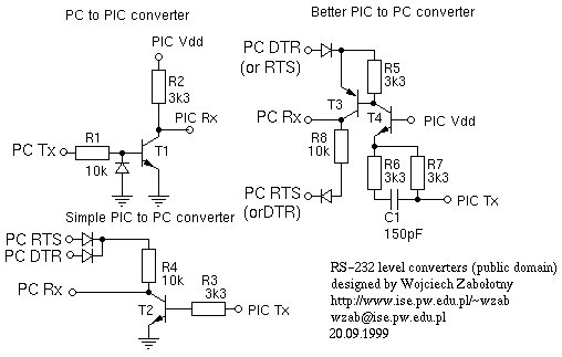
- Use a TTL HI output for the RS232 GND: Steve Walz of armory.com says “Use a TTL HI output for the RS232 *GROUND*!! Then you get +/-5VDC levels to fake out the RS232. When TTL-GND goes HI, then a TTL-XMT LO looks like -5VDC and a “mark”. Even sign problems go away in hardware! When TTL-GND goes LO, and TTL-XMT goes HI, it looks like +5VDC and a “space”! You can derive the two TTL signals from one off an inverter or inverter pair! Then magically, you have direct TTL to RS232 conversion!!
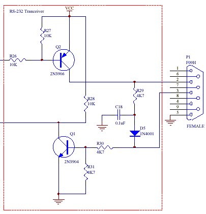
M. Adam Davis points out that we should “Just *make sure* the power supply of the pic and/or the power supply of the other rs-232 device are not grounded. ie, my bench power supply has +5v and ground, but the ground is grounded to the house ground, SO is the computer’s rs-232 port. I can’t use this trick without isolation. This also means that any interaction with other external devices requires some thoughtful planning.” [Ed: this is only true if the devices confuse signal ground and chassis ground. Remember that ground is at DB25 pin 7, and not pin 1 Pin 1 is chassis ground, not signal ground.]
Bob Ammerman [RAMMERMAN at PRODIGY.NET] of RAm Systems says:
Here is a neat trick to get a ‘push-pull’ output from two PORT A pins:1: define them as analog (ADCON1)
2: TRIS them as outputs.Now, when you BSF either of them the other will automatically be cleared.
Andrew Warren says:
Of course, if you can’t configure the pins as analog inputs (because, for instance, the PIC you’re using doesn’t HAVE an A/D converter), you can do this:
        MOVLW   00000001B       ;RA0 = 1, RA1 = 0.
        MOVWF   PORTA           ;

        MOVLW   00000011B
        XORWF   PORTA           ;Toggle RA0 and RA1.
        XORWF   PORTA           ;Toggle the two pins again.
        XORWF   PORTA           ;And again...
Or, if those two pins are the only ones defined as outputs on that port:
        MOVLW   00000001B       ;RA0 = 1, RA1 = 0.
        MOVWF   PORTA           ;

        COMF    PORTA           ;Toggle RA0 and RA1.
        COMF    PORTA           ;Again.
        COMF    PORTA           ;And again...
For more detail: TTL to RS232 Signal Conversion
- How can TTL be used to fake RS232 voltage levels?
By driving the RS232 ground with a TTL HI and using a TTL transmit that goes LO to appear as -5V (mark) and HI to appear as +5V (space). - Can you derive the two required RS232-polarity signals from one TTL pin?
Yes; you can derive complementary signals using an inverter or an inverter pair from one TTL signal. - Does this TTL-ground trick require isolation of power supplies?
Yes; you must ensure the PIC power supply and the other RS232 device supply are not grounded together, otherwise isolation is required. - Which DB25 pin is signal ground for RS232?
DB25 pin 7 is the signal ground; pin 1 is chassis ground. - How can you get a push-pull output from two PIC PORTA pins?
Configure the pins as analog (ADCON1) and TRIS them as outputs; setting one will clear the other, producing push-pull behavior. - What if the PIC has no A/D converter to set pins as analog?
Use instruction sequences such as MOVLW/MOVWF combined with XORWF or use COMF on PORTA to toggle and produce complementary outputs. - How does making TTL-GND HI affect TTL-XMT levels electrically?
When TTL-GND is HI, a TTL-XMT LO appears negative (about -5V) as a mark, and when TTL-GND is LO with TTL-XMT HI it appears positive (about +5V) as a space. - Are there interaction concerns with other external devices when using this trick?
Yes; interactions require planning because grounded supplies or shared chassis grounds can interfere with the TTL-ground method.

