Overview
Trinket lends itself very well to building clock projects, its small and easy to hide behind a larger display. And clocks don’t need a lot of logic, this example only has maybe 20 lines of code. Adding a digital display via I2C is possible using seven segment or character-based displays (with the library code posted for other projects).
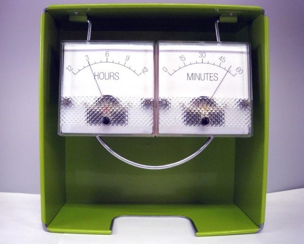
This project interfaces Trinket to the the Adafruit DS1307 real-time clock (RTC) breakout board to form a clock. But in a twist, the display is done using two analog meters. One for hours, one for minutes.
The Trinket can output to a meter without digital to analog converters. Trinket has pulse width modulation (PWM) on three of its pins. The meter uses a moving coil inductance movement, acting to average the indication of current flowing through it. If you have narrow pulses, the average voltage it sees is lower, thus the current is lower for the fixed resistance attached to it. For wide pulses, the meter sees nearly the supply voltage and will stay around the full scale. This circuit varies the pulse width sent to the meters proportional to the hour of the day and the minutes after the hour.
For two meters, we will use two of the three PWM pins on Trinket (the third is also an I2C pin connected to the clock module).
There are several projects on the web using analog meters to tell time. The ease at which you can do this with Trinket allows you to build this type of clock quickly and compactly. You may focus on designing how to mount the meters in a creative way.
There are many ways to display the finished project. Rather than a cabinet or plexiglass display, I chose meters free-floating in a colorful box. I think it lends a modern look.
Building the Circuit
Start by unpacking your Trinket. If you will use a breadboard or Perma-Proto board, you will want to solder on the header pins (provided). See Introducing Trinket on doing this and general information.
Unpack your DS1307 kit. This requires assembly also. Please follow the DS1307 Real Time Clock Breakout Board Kit tutorial on building your clock module.
Trinket can be powered from 3.7 to 16 volts via the BAT+ input and ground. This makes powering the clock very flexible. For this project, I chose the 5V Trinket as the DS1307 board has a 5 volt input which may be connected to the 5V output pin on Trinket. If you use another RTC module that works at 3.3 volts, the Trinket 3V may be used with appropriate changes to the meter calibration. I show powering via DC supply (wall wart). Battery use will vary depending on the batteries you choose. A 9 volt battery will not last very long and is not recommended.
For a 5 volt Trinket and 50 microamp meters, for full scale deflection we need a series resistor on each meter to keep the current less than or equal to the maximum current the meter can handle. Using Ohm’s law, R = V / I = 5 / .00005 = 100,000 ohms (100 K). You will need two of these resistors, preferably 5% or better tolerance. These are commonly available from electronics suppliers. If you want precision in calibrating the meter, you may want to substitute each resistor with a 100K potentiometer with a series resistor, perhaps 10 to 47 K. This allows for tuning the resistance. When I designed the project, the 100K resistors gave accurate enough time without needing potentiometers.
Preparing to Code
To prepare the Trinket for other programs, you will want to first load the Trinket Blink sketch into the Arduino software then load it onto the Trinket to verify everything works well. You must press the hardware reset button on the Trinket then quickly press upload in the Arduino software to upload a sketch. If you get an error, try the reset-upload process again. If you continually cannot load the blink sketch, check to make sure the Trinket is connected (without any wires connected to pins #3 and #4) and the Arduino IDE software has all the required changes.
Once the Blink sketch works, you should install the TinyRTClib and TinyWireM libraries. Installation of the libraries is as follows:
- Visit each of the code pages at Github.com: TinyRTClib and TinyWireM
- Select the “Download ZIP” button
- Uncompress each ZIP file after it’s finished downloading.
- The resulting folder should contain the code files and an “examples” sub-folder. Sometimes in Windows you’ll get an intermediate-level folder and need to move things around.
- Rename the TinyWireM library folder (containing the .cpp and .h files) to “TinyWireM”, and place it alongside your other Arduino libraries, typically in your (home folder)/Documents/Arduino/Libraries folder. Libraries should not be installed alongside the Arduino application itself.
- Do the same for the TinyRTClib library.
- Re-start the Arduino IDE if it’s currently running.
Here’s a tutorial that walks through the process of correctly installing Arduino libraries.
Now you are ready to copy the sketch on the next page for your clock.
Debugging Issues
For errors in the Arduino IDE software:
- Ensure you have installed Trinket extensions, the USBtinyISP driver, and changed the ld.exe program as listed in the Introducing Trinket tutorial.
- Ensure you have installed both the TinyWireM and TinyRTClib libraries..
- Ensure you push the Trinket on board reset button before uploading your sketch, the red LED will blink when ready for upload, there is a 10 second window to do this.
- If you place a large amount of code or other libraries in a sketch, it is very easy to exceed the available code space on the Trinket. If your program absolutely will not fit, consider switching to an Arduino Uno, Adafruit Boarduino, Pro Trinket, or Adafruit Flora with standard libraries.
- If you get errors similar to the one below, you may have included decimal numbers and the floating point library was added by the Arduino IDE, exceeding the amount of program space available.
arduino-1.0.1/hardware/tools/avr/bin/../lib/gcc/avr/4.3.2/../../../../avr/lib/avr25/crttn85.o:(.init9+0x2):relocation truncated to fit: R_AVR_13_PCREL against symbol `exit’ defined in .fini9 section in /arduino-1.0.1/hardware/tools/avr/bin/../lib/gcc/avr/4.3.2/avr25\libgcc.a(_exit.o)
The code on the next page still leaves a good deal of space for additional functionality, especially once the serial code is no longer needed. If you declare large arrays, define large text strings, add decimal/floating point numbers, or other libraries, the space may fill up or overflow.
Code
If you plan to have the code function differently than the sample or have problems you want to debug, having a serial monitor will help. I have tried the SendOnlySoftwareSerial library available in this arduino.cc post with good results. It adds about 1300 bytes of overhead so you will want to comment out the serial code in your sketch when you do not need it.