
Summary of Top PIC Microcontroller Projects with Embedded C Programming
Peripheral Interface Controller (PIC) microcontrollers are versatile, reprogrammable embedded controllers with Harvard architecture, internal RAM, EEPROM, Flash, peripherals (10-bit ADC, timers, comparator, watchdog), and various package types. The article outlines a project controlling a DC motor's forward/reverse direction using a PIC (PIC16F877A), a crystal oscillator, reset circuit, push-button inputs, and an L293D driver. It covers circuit design (4 MHz crystal with capacitors, reset RC), Proteus simulation steps, and MPLAB + CCS C compiler programming workflow.
Parts used in the PIC DC Motor Direction Control Project:
- PIC16F877A microcontroller
- Electric DC motor
- L293D motor driver IC
- Crystal (4 MHz)
- Capacitors (20 pF to 40 pF for crystal)
- 10 kΩ resistor (for reset)
- 10 μF capacitor (for reset)
- Resistors (general)
- Capacitors (general)
- 5 V DC power supply
- Push-button switches (for input interrupts)
Peripheral Interface controller (PIC) family is one of the most powerful advanced microcontroller which is developed by the microchip technology with Harvard architecture, i.e., it has a minimum set of instructions. The PIC microcontroller projects are programmed with the embedded C programming language. PIC devices consist of powerful featured controller with an internal RAM, EEPROM, Flash memory and other peripheral units.
PIC microcontroller comprises a 10 bit ADC, 2timers, high current I/O ports a comparator and a watchdog timer. The PIC microcontrollers come with various forms such as PIC32 bit, 16bit, 8bit depending on the specific PIC microcontroller family. Most of the industries widely use this controller in embedded applications because it can be easily reprogrammed using flash memory.
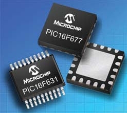
PIC Chip
The PIC chip is nothing but a package which is integrated with thousands of basic electronic components such as transistors, diodes, resistors and capacitors. The integrated circuits are shielded in such a way that these are quite easy to handle and thus protect the devices from damages. These microcontrollers are available in many different types of IC packages – but each has its own advantage and disadvantage. The most popular IC is Dual-In-line Package (DIP), used mostly in any embedded system design applications. Some of the configurations include:
- DIP (Dual In-Line Package)
- SOIP (Small Outline Integrated Circuit)
- PLCC (Plastic Leaded Chip Carrier)
- TQFP (Tin Quad Flat Package)
- PAG (Pin Grid Array)
Step-by-Step Procedure for developing a PIC Microcontroller Project
We often use microcontroller for embedded applications as a controller to control any actuators such as motors and displays, and so on. Many of you would love to build your own embedded systems and feel confident if you could build your own embedded systems. Therefore, for your ease, this simple project using a PIC microcontroller is the best option. Now for this, you need to have a basic idea about each step required to develop a PIC microcontroller based projects. Therefore, for your understanding, the following explanation along with the basic steps to build a microcontroller based project is given in detail.
Here, you can follow the project that controls the direction of DC motors by using a PIC microcontroller.
Basic Idea behind the Design
The microcontroller generates the output logic pulses based on the input push-button switches. In this system, the DC motor rotates in the forward and backward directions when the push button creates interrupts signal. The Crystal interfaced to the input pins of the microcontroller provides accurate clock signals at the crystal frequency.
Steps for Developing the Project
Step1: Circuit Designing
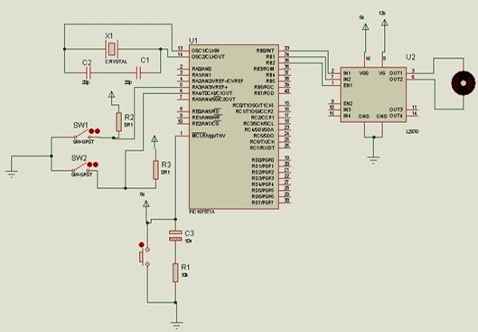
The PIC microcontroller crystal operates at 4 MHz frequency because it gives exact clock pulses for data synchronization. Two capacitors are connected to the crystal oscillator with a range of 20pf to 40pf which is used to stabilize the clock signals. The PIC microcontroller sometimes goes to a block state or missing time calculation; at that time, we need to reset the microcontroller. When the microcontroller is reset, it takes maximum 3sec time delay with the help of the 10k resistor and 10uf capacitor.
Circuit Components
1. Hardware Components
- Electric DC Motor
- Crystal
- Reset
- PIC Microcontroller
- Resistors
- Capacitors
2. Software Components
- MPLAB Compiler
- Proteus software
- Embedded C language
Circuit Connections
The 5v DC supply is given to the 40 pin of the microcontroller that drives the circuit. The crystal is connected to the 13 and 14 pin of the microcontroller. The reset circuit is interfaced at 1 pin of the microcontroller. The DC motor is connected to the pin RB0, RB1, RB2 of the microcontroller through a L293D driver IC.
Step 2: Circuit Drawing
Before implementing the hardware of this project, we have to simulate this in software. This circuit is designed with the help of Proteus software. It is a circuit designing software that contains a database of components which can be used to build the circuit.
- Open the Proteus software. A window with a menu bar appears.
- Click the file menu.
- Select new design from the drop-down menu, and then click the library menu.
- Select pick devices/symbol from the drop-down menu.
- Select the relevant comment by double clicking on it, so that the component appears on the window.
- Add all the electronic components and draw the circuit with proper connections, as shown in the figure.
 Step3: PIC Microcontroller Programming
For programming a PIC microcontroller, the MPLAB software is used, and this software is available in different versions.
- First open the MPLAB software. This shows the menu bar with the file, edit, view, project and tools options.
- Select the project option and select the ‘project wizard option’ from the drop-down menu. Select a microcontroller for your project. Select the exact type of microcontroller from the drop-down menu (select PIC16f877A microcontroller).
- Click ‘Next step’ and select the language tool suite from the project wizard menu. Select compiler of your project, i.e., CCS C compiler.
- Click next step and give a name to the project as well as set the location and click the save button to save the project. A folder with the name ‘source group is created’ in the folder.
- Click the ‘File’ menu on the menu bar. Select a ‘New file’ from the drop-down menu.
- Write the code on the blank space, which is given below for this project.
For more detail: Top PIC Microcontroller Projects with Embedded C Programming
- What microcontroller is selected for the project?
The article uses the PIC16F877A microcontroller for the project. - How is the DC motor controlled by the PIC?
The PIC generates output logic pulses based on push-button inputs and drives the DC motor through an L293D driver to rotate forward and backward. - What clock frequency is used for the PIC crystal?
The crystal operates at 4 MHz to provide accurate clock pulses. - Which software is used to simulate the circuit?
The Proteus software is used to draw and simulate the circuit. - Which IDE and compiler are used for programming the PIC?
MPLAB IDE is used with the CCS C compiler as the language tool suite for the project. - Where are the crystal pins connected on the PIC?
The crystal is connected to pins 13 and 14 of the microcontroller. - How is the reset implemented for the PIC?
The reset circuit uses a 10 kΩ resistor and a 10 μF capacitor and is connected to pin 1 of the microcontroller. - Which pins drive the DC motor through the L293D?
The DC motor is connected through the L293D driver IC to pins RB0, RB1, and RB2 of the microcontroller.
