Summary of Time-Controlled Switch Using PIC16F72
This article describes a time-controlled switch using a PIC16F72 microcontroller to automatically operate appliances for 1–99 minutes. It features manual reset, time setting via buttons, and dual 7-segment displays. The circuit steps down 230V AC to 12V, regulates it, and drives a relay to control the load. This system saves power and extends appliance life by eliminating manual monitoring.
Parts used in the Time Controlled Switch:
- PIC16F72 microcontroller (IC1)
- Regulator 7805 (IC2)
- Two 7-segment displays (LTS542)
- 4MHz quartz crystal
- Switches S2, S3, S4, and S5
- Transistor T1
- 12V relay RL1
- Diode D5
- Transformer X1
- Full-wave rectifier diodes D1 through D4
- Capacitors C4 and C5
- LED1 and LED2
- Resistor R19
- Single-side PCB
A time controlled switch is an automatic timer switch that turns an appliance ‘on’ for the desired time duration. After the preset time duration, the timer automatically switches off, disconnecting the appliance from the power supply. The time duration for which the appliance should be ‘on’ can be set from 1 to 99 minutes.
This switch obviates the need to continuously monitor the appliance—an advantage over the manual switch. It can be used to switch on or switch off any electrical home appliance at a predetermined time. Switching an appliance on or off in a timely manner increases the life of the appliance and also saves power consumption.
The switch also finds industrial applications, where the machines which control the processes can be run for the desired time.
Time controlled switch circuit
Fig. 1 shows the circuit of the time controlled switch using PIC16F72 microcontroller. It comprises microcontroller PIC16F72 (IC1), regulator 7805 (IC2), two 7-segment displays//electronicsforu.com/resources/7-segment-display-pinout-understanding(LTS542) and a few discrete components.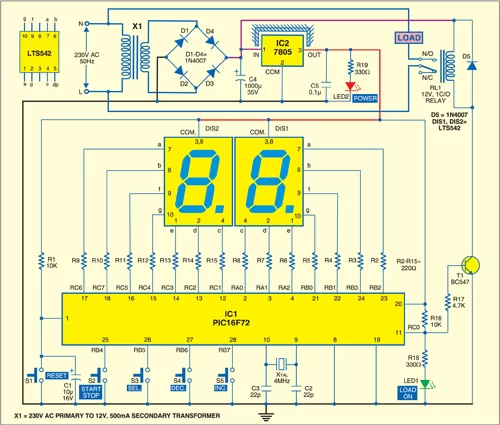
Microcontroller PIC16F72 is the heart of this time controlled switch. It is an 8-bit, low-cost, high-performance, flash microcontroller. Its key features are 2 kB of flash program memory, 128 bytes of RAM, eight interrupts, three input/output (I/O) ports, three timers and a five-channel 8-bit analogue-to-digital converter (ADC). There are 22 I/O pins, which are user-configurable for input/output on pin-to-pin basis. Architecture is RISC, and there are only 35 powerful instructions.
System clock plays a significant role in operation of the microcontroller. A 4MHz quartz crystal connected between pins 9 and 10 provides the basic clock to the microcontroller (IC1).
Two 7-segment displays (DIS1 and DIS2) are used to display the time in minutes. Port pins RB2, RB3, RA0, RA1, RA2, RB1 and RB0 are connected to segment pins ‘a’ through ‘g’ of display DIS1, respectively. Ports pin RC6, RC7, RC1, RC2, RC3, RC5 and RC4 are connected to segment pins ‘a’ through ‘g’ of display DIS2, respectively.
Switches S2 (start/stop), S3 (select), S4 (decrement) and S5 (increment) are connected to port pins RB4 through RB7 of the microcontroller, respectively. Port pin RC0 of the microcontroller is used to control relay RL1 with the help of transistor T1. When port pin RC0 is high, transistor T1 drives into saturation and 12V-relay RL1 energises to connect the load to power supply. Diode D5 acts as a free-wheeling diode.
Circuit Operation
To derive the power supply for the circuit, the 230V, 50Hz AC mains is stepped down by transformer X1 to deliver a secondary output of 12V, 500mA. The transformer output is rectified by a full-wave rectifier comprising diodes D1 through D4, filtered by capacitor C4 and regulated by IC 7805 (IC2). Capacitor C5 is used to bypass the ripples present in the regulated supply. LED2 gives power-‘on’ indication. Resistor R19 limits the current through LED2. Switch S1 is used for manual reset.
Set the time using switch S4 for decrement and switch S5 for increment. The time is indicated on 7-segment displays DIS1 and DIS2. To start timing count-down, press start/stop switch S2. Relay RL1 energises to switch on the appliance and LED1 glows. If you press start/stop switch S2 again, the count-down process will stop and relay RL1 de-energise to switch the appliance off.
Construction and working
A single-side PCB for the microcontroller-based time controlled switch is shown in Fig. 2 and its component layout in Fig. 3.
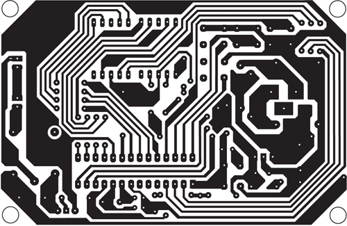
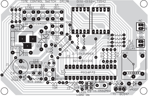
Download PCB and component layout PDFs: click here
Assemble the circuit on a PCB to minimise time and assembly errors. Carefully assemble the components and double-check for any overlooked error. Use an IC base for microcontroller. Before inserting the IC, check the supply voltage.
The time controlled switch works in two modes: setting mode (to set the time from 1 to 99 minutes) and working mode (to drive the load for the desired time as per the setting). The modes can be changed using switch S3. When LED1 glows, it indicates that the system is in working mode. If LED1 is off, the system is in setting mode.
Setting mode
By default, when the microcontroller is powered up, it is in setting mode. In this mode, one of the two 7-segment displays should blink with a random digit, say, 6. You can change the blinking digit to any digit from 0 through 9 using decrement switch S4 or increment switch S5. You can also shift the blinking digit from DIS1 to DIS2 or vice-versa using switch S3. Thus the desired time can be set using switches S3, S4 and S5.
After setting the desired time, press start/stop switch S2 to switch from setting mode to working mode. The appliance will turn on for the preset time unless you press switch S2 again to stop the operation in between.
- What is the primary function of this time controlled switch?
It turns an appliance on for a desired duration between 1 and 99 minutes and then automatically switches it off. - How can the time duration be set?
The time is set using decrement switch S4 and increment switch S5 while in setting mode. - Which component serves as the heart of the circuit?
The PIC16F72 microcontroller acts as the core of this time controlled switch. - How does the circuit indicate the working mode?
LED1 glows when the system is in working mode, while it remains off during setting mode. - What provides the basic clock signal to the microcontroller?
A 4MHz quartz crystal connected between pins 9 and 10 provides the basic clock. - Can this device be used for industrial applications?
Yes, it can run machines that control processes for a desired time in industrial settings. - How is the 230V mains voltage converted for the circuit?
Transformer X1 steps down 230V AC to 12V, which is then rectified and regulated. - What happens when start/stop switch S2 is pressed again after starting?
Pressing S2 again stops the countdown process and de-energizes the relay to switch the appliance off.