This post would provide a working example of how to make a simple Current Meter (DCM) using 16bit PIC microcontroller and a series shunt resistance. We have very precise ammeter current measurement with a 10bit ADC and with a tolerance of ±10mA.
You may download code and Proteus Simulation from the download section at the bottom of this post. I am using MPLAB X IDE, C30 Compiler and Proteus Simulation on v8.0. This code is written in C Language and will work on PIC24, DsPIC33 and DsPIC30 (16bit microcontroller) by slightly changing the code.
In this post I supposed that you know following things if not then please go through following posts before proceeding with this.
· How to Blink an LED. (Click here)
· How to interface an LCD. (Click here)
· How to configure ADC module. (Click here)
· Digital Voltmeter. (Click here)
The science behind measuring current is to add a known shunt resistance in the path from which current is flowing so the voltage drop on this shunt resistance is measured by ADC channel. By using Ohm’s Law we can find the current in particular path (As current is same in a loop). This shunt resistance is very small of some milliohms with higher wattage typically 1-10W depending upon particular application.
Proteus Simulation:
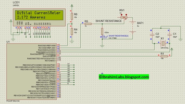
In the following figure 1. I used a fix resistor (R4 = 10kΩ and R6 = 10kΩ) for 2.5V reference voltage for ADC. And a dummy variable resistor for simulating this circuit for various current measurements. A shunt resistance with a resistance of 100mΩ is used in series with the path in which we are going to measure current. I am using ADC channel AN1 for measurement of voltage drop across shunt resistance. I used LCD on PortB.
In the following figure 2. Animation shows that when I increase/decrease resistance from variable resistor RV1 the current in the path changes as shown by a current probe named shunt resistance. And the value that is measured by current probe is same as that we measured through ADC and is displayed on LCD with a tolerance of ±10mA.
Code:
In the following figure 3. This is main function in which I first initialize LCD, then I configure ADC with Channel 1. And a loop which only calls a function named DisplayCurrent() which is responsible for displaying measured current flowing through shunt resistance on LCD.
For more deail: Simple Digital Current Meter (DCM) using PIC microcontroller (Schematic + code + Proteus simulation)


