Summary of Simple 2×32 Watt Audio Amplifier with TDA2050
This article details the design and construction of a 32+32 Watt audio amplifier using the TDA2050 IC. It covers transformer selection (12-0-12V, 6A), thermal calculations for an aluminum heat sink, and component value derivations for gain, input filtering, bandwidth enhancement, and Zobel networks to ensure stability and audio quality.
Parts used in the TDA2050 Audio Amplifier:
- TDA2050 Integrated Circuit
- 12-0-12 Volt Transformer (6 Amp rating)
- Aluminum extrusion heat sink
- Elastomer heat transfer pad
- Resistors (including 22kΩ and 680Ω)
- Ceramic and Metal film oil capacitors
- Zobel network components (2.2Ω resistor and 0.1uF capacitor)
- Dual polarity power supply with decoupling capacitors
- 4Ω woofer or loudspeaker
If you are thinking about building a simple, cheap, and moderately high power amplifier circuit that can deliver up to 50-watt peak RMS power into a loudspeaker, then you are in the right place. In this article, we are going to use the most popular TDA2050 IC to design, demonstrate, build, and test the IC to achieve the above requirements. So without further ado, let’s get started.
Also, check our other Audio amplifier circuits where we have built 25w, 40w, 100w audio amplifier circuit using op-amps, MOSFETs, and IC like IC TDA2030, TDA2040.
Before we start
Before you start building this 32+32 Watt Audio Amplifier, you should know how much power your amplifier can deliver. Also, you need to consider the load impedance of the speaker, woofer or anything that you are building your amplifier. For more information, consider reading the datasheet.
By going through the datasheet, I have found that the TDA2050 can output 28 Watts into 4Ω speakers with 0.5% distortion on a 22V power supply. And I will be powering a 20-watt woofer with 4Ω impedance, which makes the TDA2050 IC a perfect choice.
Choosing the Transformer
The sample circuit on the datasheet for the TDA2050 says that the IC can be powered from a single or a split power supply. And in this project, a dual polarity power supply will be used to power the circuit.
The goal here is to find the right transformer, which can deliver sufficient voltage and current to drive the amplifier properly.
If we consider a 12-0-12 transformer, it will output 12-0-12V AC if the input supply voltage is 230V. But as AC mains input always drifts, so the output will also drift. Taking that fact in mind, now we can calculate the supply voltage for the amplifier.
The transformer gives us AC voltage and if we convert that into DC voltage we will get-
VsupplyDC = 12*(1.41) = 16.97VDC
With that, it can be clearly stated that the transformer can deliver 16.97VDC when the input is 230V AC
Now if we consider voltage drift of 15%, we can see that the maximum voltage becomes-
VmaxDC = (16.97 +2.4) = 18.97V
Which is well within the maximum supply voltage range of the TDA2050 IC.
Power Requirement for TDA2050 Amplifier Circuit
Now let us determine how much power will be consumed by the amplifier.
If we consider the power rating of my woofer, it is 20 watts, so a stereo amplifier will consume 20+20 = 40 watts.
Also, we have to consider the power losses and the quiescent current of the amplifier. Generally, I do not calculate all these parameters because to me it’s time-consuming. So as a rule of thumb, I find the total consumed power, and multiply it by a factor of 1.3 to find out the output power.
Pmax = (2x18.97)*1.3 = 49.32 watt
So, to power the amplifier circuit, I am going to use a 12 – 0 – 12 transformer, with 6 Amps rating, this is a bit of overkill. But at the moment, I do not have any other transformer with me so I am going to use that.
Thermal Requirements
Now, that the power requirement for this Hifi Audio Amplifier is out of the way. Let us turn our focus to finding out the thermal requirements.
For this build, I have chosen an aluminum, extrusion-type heat sink. Aluminum is a well-known substance for heat-sink because it’s relatively inexpensive and exhibits good thermal performance.
To verify the maximum junction temperature of the TDA2050 IC does not exceed the maximum junction temperature, we can use the popular thermal equations, which you can find in this Wikipedia link.
We use the general principle that the temperature drop ΔT across a given absolute thermal resistance RØ with a given heat flow Q through it is.
ΔT = Q * RØ
Here, Q is the heat flow through the heatsink which can be written as
Q = ΔT/RØ
Here, ΔT is the maximum temperature drop from junction to ambient
RØ is the absolute thermal resistance.
Q is the power dissipated by the device or heat flow.
Now for the sake of the calculation, the formula can be simplified and rearranged to
TJmax – (Tamb + ΔTHS) = Qmax * (RØJC + RØB + RØHA)
Rearranging the formula
Qmax = (TJmax – (Tamb + ΔTHS)) / (RØJC + RØB + RØHA)
Here,
TJmax is the maximum junction temperature of the device
Tamb is the ambient air temperature
THs is the temperature where the heatsink is attached
RØJC is the device absolute thermal resistance from junction to case
RØB is the typical value for an elastomer heat transfer pad for a TO-220 package
RØHA a typical value for a heatsink for a TO-220 package
Now let’s put the actual values from the datasheet of the TDA2050 IC
TJmax = 150 °C (typical for a silicon device)
Tamb = 29 °C (room temperature)
RØJC = 1.5 °C/W (for a typical TO-220 package)
RØB = 0.1 °C/W (typical value for for an elastomer heat transfer pad for a TO-220 package)
RØHA = 4 °C/W (a typical value for a heatsink for a TO-220 package)
So, the final result becomes
Q = (150 - 29) / (1.5+0.1+4) = 17.14W
This means we have to dissipate 17.17 watts or more to prevent the device from overheating and getting damaged.
Calculating the Component Values for the TDA2050 Amplifier Circuit
Setting the Gain
Setting up the gain for the amplifier is the most important step of the build, as a low gain setting may not provide enough power. And a high gain setting will certainly distort the amplified output signal of the circuit. With my experience, I can tell that a gain setting from 30 to 35 dB is good for playing audio with a smartphone or a USB audio kit.
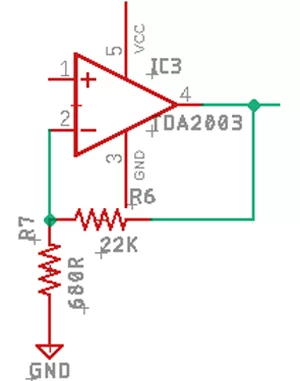
The example circuit in the datasheet recommends a gain setting of 32db and I am going to just leave it as it is.
The gain of the Op-Amp can be calculated by the following formula
AV = 1+(R6/R7)
AV = 1+(22000/680) = 32.3db
Which works just fine for this amplifier
Note: For setting up the amplifiers gain 1% or 0.5% resistors must be used otherwise the stereo channels will produce different outputs
Setting up The Input Filter for the Amplifier
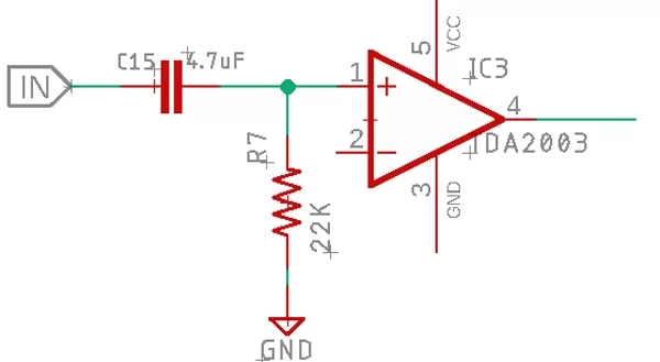
The capacitor C1 acts as a DC blocking capacitor thus reduces noise.
The Capacitor C1 and the resistor R7 create an RC high pass filter, which determines the lower end of the bandwidth.
The cutoff frequency of the amplifier can be found by using the following formula shown below.
FC = 1 / (2πRC)
Where R and C are the values of the components.
To find the values of the C, we have to rearrange the equation to:
C = 1 / (2π x 22000R x 3.5Hz) = 4.7uF
Note: It is recommended to use metal film oil capacitors for the best audio performance.
Setting up The Bandwidth in the Feedback Loop
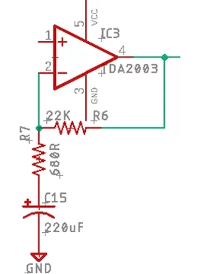
The capacitor in the feedback loop helps to make a low pass filter, which helps to enhance the bass response of the amplifier. The smaller the value of the C15, the softer the bass will get. And a larger value for C15 will give you a more punchy bass.
Setting the Output Filter
An output filter or commonly known as a Zobel network prevents oscillations generated from the speaker coil and wires. It also rejects the radio interference which is picked up by the long wire from the speaker to the amplifier; it also prevents them from going into the feedback loop.
The cutoff frequency of the Zobel network can be calculated by the following simple formula
The datasheet gives values for the R and C, which is R6 = 2.2R and C15 = 0.1uF If we put the values in the formula and calculate we will get a cut-off frequency of
Fc = 1 / (2π x 2.2 x (1 x 10^-7))
= 723 kHz
723 kHz is above the human hearing range of 20 kHz, so it will not affect the output frequency response and it will also prevent wired noise and oscillations.
The Power Supply
A dual polarity power supply with proper decoupling capacitors is required to power the amplifier, and the schematic is shown below.
Source: Simple 2×32 Watt Audio Amplifier with TDA2050
- What is the maximum power output of the TDA2050 IC?
The datasheet indicates the TDA2050 can output 28 Watts into 4Ω speakers with 0.5% distortion on a 22V power supply. - How do you calculate the DC supply voltage from the transformer?
Multiply the AC voltage by 1.41; for example, 12V AC results in approximately 16.97VDC. - Why is a dual polarity power supply recommended for this project?
The sample circuit on the datasheet allows the IC to be powered from either a single or split power supply, and this project utilizes a dual polarity supply. - What is the best way to set the gain for playing audio with a smartphone?
A gain setting between 30 and 35 dB is recommended, with the specific circuit using 32.3 dB calculated via resistors R6 and R7. - Does the Zobel network affect the human hearing range?
No, its cutoff frequency is calculated at 723 kHz, which is well above the 20 kHz human hearing range. - Can you use standard resistors for setting up the amplifier gain?
No, 1% or 0.5% resistors must be used to prevent stereo channels from producing different outputs. - What type of capacitors are recommended for the best audio performance?
Metal film oil capacitors are recommended for the input filter capacitor C1. - How much power does the amplifier consume based on the woofer rating?
If the woofer is 20 watts, a stereo amplifier will consume 40 watts before accounting for losses.