Summary of Sending SMS Text Message using PIC Microcontroller – Flowcode
A GSM modem communicates over mobile networks using serial AT commands, enabling microcontrollers like PIC to send/receive SMS and perform remote monitoring, alarms, or SMS gateways. Interfacing is via USART (RX/TX) or vendor boards like SmartGM862 and E-blocks that simplify connections. Key AT commands include ATI, ATE0/1, AT+CMGF, AT+CMGS, and AT+CMGR. Using Flowcode, initialize the GSM component, check network registration, set SMS to Text mode (AT+CMGF=1), then send messages. PDU mode (AT+CMGF=0) uses hex encoding, while Text mode sends readable messages up to 160 characters.
Parts used in the PIC GSM SMS Project:
- PIC Microcontroller (with USART)
- GSM modem or GSM module
- GSM antenna
- SIM card
- Connection cables (for RX/TX)
- SmartGM862 development board (example)
- E-blocks GSM board (example)
- Voltage regulator (on some GSM boards)
- Speaker and microphone terminals (on SmartGM862)
- PCB antenna (on E-blocks)
Figure 1: Controlling and Monitoring devices with a Cellphone
A GSM modem is a wireless modem that works with a GSM wireless network. GSM stands for Global System for Mobile communications, this architecture is used for mobile communication in most of the countries in the world.
A wireless modem acts basically like the traditional dial-up modem, the main difference is that a dial-up modem sends and receives data through a fixed telephone line while a wireless modem sends and receives data through radio waves. Besides the dial-up connection, GSM modem can also be used for sending and receiving SMS which is also one of the key features of GSM modem. In this article we are going to learn how to send an SMS text Message from a PIC Microcontroller.
 Applications
- Remote System Monitoring: In a remote system monitoring application, a Microcontroller for example could be used to constantly monitor the status of a remote sensors, let say temperature, a liquid level sensor or a moisture sensor. If a certain condition is reached, the program will send an SMS to notify the situation, if these sensors are installed in a farm for example, the farmer could be notified of any situation happening in the farm about heat, moisture, drought, etc.
- Home Alarm System: When a motion sensor detects a movement of an intruder, an SMS will be sent to a predefined number which could be you or your security reaction company and a siren or any other sound device could be triggered in the process as well.
- SMS Gateway: To send and receive SMS for advertisements.
GSM Connection
It is very easy to interface a GSM Modem to a PIC Microcontroller as most GSM modems have a serial interface. The USART serial input pin RX and TX of the microcontroller are connected to the TXD and RXD pins of the GSM Modem. Some GSM modems have PCMCIA Type II or USB interfaces. Figure 2 below shows a block diagram of a GSM module connected to USART module of a PIC Microcontroller.
Figure 2: GSM module connected to a PIC Microcontroller
>>> To learn more on Serial Communication: PIC Microcontroller Communication with RS232 Bus
There are GSM board on the market that one can use to quickly interface to a PIC. The SmartGM862 Board from Mikroelekronika and the E-blocks GSM board from Matrix Technology Solutions are just a few examples of many boards. The SmartGM862 is a full-featured development tool for Telit GM862-QUAD GSM/GPRS module or the GM862-GPS version. It features GM862 module connector, voltage regulator, antenna holders, speaker and microphone screw terminals and more. DIP switch is provided for configuring UART communication lines with the target microcontroller. It can be connected to development boards via IDC10 connector.
Figure 3: Connecting the SmartGM862 Board to EasyPIC7 V7 Development Board
The E-blocks GSM board allows easy access to the mobile phone GSM/GPRS networks. The on board GSM/GPRS module can be used to make or receive wireless voice calls and is also capable of sending and receiving SMS text messages. The GSM/GPRS E-block comes complete with on board PCB antenna, SIM card socket, 2.5mm audio jacks for MIC and Headphone audio connection and LED to display the network connection status.
GSM Commands
The AT commands are used to control modems which are communicated through serial communication with a microcontroller or a PC. AT is the abbreviation for ATtention. These commands come from Hayes commands that were used by the Hayes smart modems in late 1970s. The Hayes commands started with AT to indicate the attention from the MODEM followed by a number of characters specifying the command tail.
AT commands with a GSM/GPRS MODEM or mobile phone can be used to check the modem settings, to change the modem settings, to issues commands like to send an SMS, read an SMS and so on.
Below is a short list of commonly used general purpose AT commands. The command should be followed by a carriage return :
- ATI: Modem product information
- ATE0: Disable echo so that characters typed by the user are not echoed back by the modem.
- ATE1: Enable the echo mode
- AT+CMGF: Select SMS message format
- AT+CMGS: Send SMS message
- AT+CMGR: Read SMS message
For more info, you can check your modem datasheet or the AT Commands Reference Guide
In the Interfacing GSM Modem with PIC Microcontroller using Flowcode tutorial, we have learnt how to use the Flowcode GSM component to send/receive AT Commands. provides a component for GSM communication. The GSM component is designed to be used with any GSM device that accepts standard GSM AT commands.
Sending an SMS from a microcontroller is very easy, just follow these few steps:
Step 1: Initialize GSM
Call the Initialize GSM macro. This macro Initializes the GSM component ready for use. It is recommended that you place the Initialize macro at the start of a program to ensure the component is initialized before being used.
 Step 2: CheckNetworkStatus
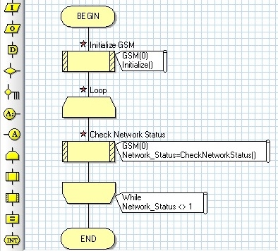
Call the CheckNetworkStatus macro. This macro checks to see if the GSM module is correctly registered on the network. This macro could be used in a while loop to wait until the GSM module has correctly registered to the network before sending other commands. This macro will return 1 if the GSM is connected to the network or will returns 0 if the GSM is not connected to the network.
Figure 5 below shows how this macro could be used in a while loop to wait until the GSM module has correctly registered to the network.
Step 3: Set SMS mode to Text Mode
Send the command to set the SMS mode to Text Mode. There are two modes of sending and receiving SMS messages with AT Commands: The Text mode and the PDU (Protocol Description Unit) mode. In PDU mode, the SMS is sent in a series of hexadecimal string of characters, at the receiving end these hexadecimal string of characters have to be decoded to extract the message in a readable format. In Text mode, the SMS is sent like the normal SMS we are used to with our cellphones. The text message can consist of alphanumeric characters with up to 160 characters long with 7-bit coding and up to 140 characters in 8-bit coding.
To set the mode to Text, the AT command is: AT+CMGF=1 and to set the mode to PDU the command is: AT+CMGF=0. The modem should respond with “OK”.
For more detail: Sending SMS Text Message using PIC Microcontroller – Flowcode
- How do you connect a GSM modem to a PIC Microcontroller?
Connect the PIC USART RX and TX pins to the GSM modem TXD and RXD pins respectively; some boards use IDC or USB/PCMCIA interfaces. - Can a PIC Microcontroller send SMS using a GSM modem?
Yes; the microcontroller sends AT commands over serial to instruct the GSM modem to send SMS messages. - What AT command sets SMS mode to Text?
Use AT+CMGF=1 to set SMS mode to Text mode. - How can the GSM module be checked for network registration?
Call the CheckNetworkStatus macro which returns 1 if connected or 0 if not; it can be used in a loop to wait for registration. - What are common AT commands used with GSM modems?
Common commands include ATI, ATE0, ATE1, AT+CMGF, AT+CMGS, and AT+CMGR. - What is the difference between Text mode and PDU mode for SMS?
Text mode sends readable alphanumeric messages (AT+CMGF=1); PDU mode sends hexadecimal encoded strings (AT+CMGF=0) that require decoding. - Where should Initialize GSM be placed in a program?
Place the Initialize GSM macro at the start of the program to prepare the GSM component before use. - What example development boards were mentioned for GSM interfacing?
The SmartGM862 board from Mikroelektronika and the E-blocks GSM board from Matrix Technology Solutions were mentioned.