Summary of SD Memory Card Interface using pic microcontroller
This article describes a hardware project enabling serial communication with SD memory cards via a PIC16F819 microcontroller. The device converts ASCII commands into SPI signals to read and write data, utilizing a voltage-level shifting circuit to interface 5V logic with 3.3V card requirements. It supports various terminal-based commands for selecting, writing, reading, and clocking the card.
Parts used in the SD Memory Card Interface Project:
- SD memory cards (under 1GB)
- SparkFun Electronics SD sockets
- PIC16F819 microcontroller
- Single-sided PCB board
- Red LED
- 1k/2k voltage divider resistors
- Terminal program software
SD memory cards, especially the ones under 1GB are cheap, relatively easy to interface and provide vast amounts of memory for imbedded control.
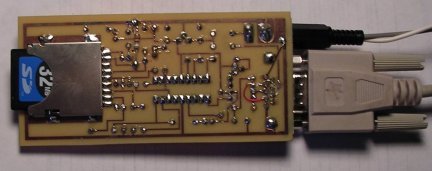
This device lets you ‘talk’ to sd cards through your serial port. Communication is in ASCII so you just need a terminal program to access it. (Note: the photos shown are of the rev-1 device with various changes, documentation is for the rev-2).
 The Hardware
SD sockets are available from SparkFun Electronics. The socket needs to be surface mounted so it was placed on the foil side of the single sided board (mouseover image above to see). The connections are close to 0.1 inch centers, so the layout was not difficult.
The PIC16F819 was chosen for its hardware support for SPI. (SD cards will usually work through an SPI interface) Running at 20Mhz, the SPI port clocks data at 5Mhz, and the serial communication is able to run at 115200 baud in software.
A quick look at the schematic shows one way to interface the 5 volt PIC to the 3.3 volt SD card. A red LED drops the 5 volt supply by about 1.8 volts to feed about 3.2 volts into the card. This is within the operating range.
Signals from the PIC go through a 1k/2k voltage divider to feed signals to the card. Signals back from the card feeding SDI input are a problem because the PIC uses schmit-trigger inputs in SPI mode requiring 3.5 volts for the high level. The circuit provides a 0.6 volt shift so the output of the card back to the PIC ranges from 0.6 to 3.8 volts. Cheesy, but it works.
The Software
The main issue with the software is configuring the SPI port. After a lot of diddling around, the proper setup seems to be: SMP=1, CLE=1, and CKP=1. See the software listing for the complete setups of SSPSTAT and SSPCON registers in sspinit. The routine that writes to the card also reads it, since, in SPI, read and write are simultaneous operations.
Once connected to a terminal program (115200 baud, 1 stop bit, no parity, no handshaking), the following commands are available:
Command Function Ctrl-C Resend last command
For more detail: SD Memory Card Interface
- How does the device communicate with the user?
Communication is in ASCII so users just need a terminal program to access it. - Why was the PIC16F819 chosen for this project?
The PIC16F819 was chosen for its hardware support for SPI which SD cards usually work through. - What method is used to power the 3.3 volt SD card from a 5 volt PIC?
A red LED drops the 5 volt supply by about 1.8 volts to feed about 3.2 volts into the card. - How are signals from the card shifted to match PIC input requirements?
Signals go through a 1k/2k voltage divider providing a 0.6 volt shift so output ranges from 0.6 to 3.8 volts. - What specific SPI port settings are required for the software?
The proper setup requires SMP=1, CLE=1, and CKP=1 in the SSPSTAT and SSPCON registers. - Can you read and write simultaneously on this SPI interface?
Yes, the routine that writes to the card also reads it since read and write are simultaneous operations in SPI. - What terminal settings should be used to connect to the device?
Users should use 115200 baud, 1 stop bit, no parity, and no handshaking. - What command selects the SD card?
The S command selects the card. - How do you resend the last command if needed?
Pressing Ctrl-C will resend the last command. - Does the documentation match the photos shown in the article?
No, the photos show the rev-1 device while the documentation is for the rev-2.