Summary of Review of EasyPIC v7
This article reviews the EasyPIC v7, a MikroElektronika development board for Microchip 8-bit PIC microcontrollers. It supports over 350 PIC models via eight DIP sockets and includes a default PIC18F45K22 chip. The board features a robust 3mm PCB, versatile power options (USB, DC jack, or terminal block), and on-board 5V/3.3V regulation. Packaging includes schematics, manuals, drivers, and demo software on a DVD.
Parts used in the EasyPIC v7:
- EasyPIC v7 development board
- PIC18F45K22 microcontroller
- Color-printed schematics
- Illustrative user's manual
- DVD with drivers and compilers
- Anti-static bag
- USB cable
- DC barrel jack
- Screw terminal block
- Jumper selection for voltage
Unpacking EasyPIC v7
EasyPIC v7 comes in a colorful and protective cardboard box that can also serve as a good storage for the development board for later use. The thing I liked most about it is that the box also contains color-printed schematics and illustrative user’s manual of EasyPIC v7 along with a DVD for installing the required drivers and programming applications. The DVD also contains demo versions of mikroElektronika’s compilers as well as plenty of code examples. The EasyPIC v7 board is packed inside an anti-static bag and an USB cable is also included in the package to connect the board to the PC.
– See more at: http://embedded-lab.com/blog/?p=8351#sthash.bJ3OVTRs.dpuf
Main Features Highlight
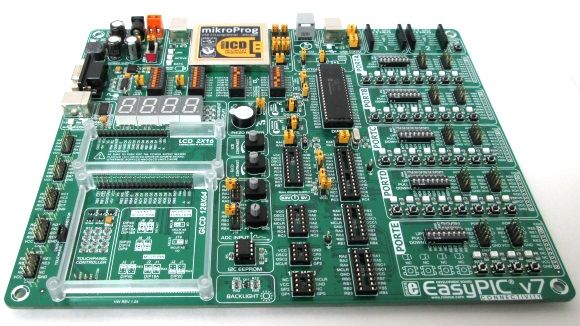
EasyPIC v7, like its predecessors, is designed for rapid prototyping and development with Microchip’s 8-bit microcontrollers. It supports over 350 PIC microcontrollers, including PIC10F, PIC12F, PIC16F, and PIC18F series, and contains 8 DIP sockets to accommodate 8-, 14-, 18-, 20-, 28-, and 40-pin count PIC MCUs. The printed circuit board of EasyPIC v7 is extra thick (~3mm) and of high quality with clearly labeled components and pin functions. The board comes with the PIC18F45K22 microcontroller plugged in by default. Here I have summarized the main features of the EasyPIC v7 development board.
– See more at: http://embedded-lab.com/blog/?p=8351#sthash.bJ3OVTRs.dpuf
Power supply
EasyPIC v7 has a 5.0V switching power supply on board along with a 3.3V regulated output. A jumper selection is provided to select between 3.3V and 5.0V power supply for operation. Thus, it can be used to develop applications for both 3.3V and 5.0V series PIC MCUs. The board can be powered through a DC barrel jack, screw terminal block, or directly through an USB cable.
– See more at: http://embedded-lab.com/blog/?p=8351#sthash.bJ3OVTRs.dpuf
- What microcontrollers does EasyPIC v7 support?
It supports over 350 PIC microcontrollers including PIC10F, PIC12F, PIC16F, and PIC18F series. - Can I use EasyPIC v7 with both 3.3V and 5.0V MCUs?
Yes, a jumper allows selection between 3.3V and 5.0V power supplies for operation. - How many DIP sockets are included on the board?
The board contains 8 DIP sockets to accommodate various pin count PIC MCUs. - What is included in the packaging besides the board?
The box contains color-printed schematics, a user manual, a DVD with drivers and code examples, an anti-static bag, and a USB cable. - Does the board come with a microcontroller installed?
Yes, it comes with the PIC18F45K22 microcontroller plugged in by default. - What are the available methods to power the board?
The board can be powered through a DC barrel jack, screw terminal block, or directly through a USB cable. - Is the printed circuit board of high quality?
Yes, the PCB is extra thick at approximately 3mm and features clearly labeled components and pin functions. - Where can I find demo versions of the compilers?
Demo versions of mikroElektronika compilers and plenty of code examples are located on the included DVD.