Summary of REMOTE CONTROLLED TOY CAR PROJECT PIC16F877 PIC16F628
This article details a remote-controlled toy car project utilizing the PIC16F877 and PIC16F628 microcontrollers. The system features a 60A motor drive circuit using N-channel FETs, an ICL7660 voltage converter, and an MC33063AP DC-DC converter for power management. It includes EEPROM storage (24C08) for configuration and supports adjustable parameters like current limits and acceleration delays. A separate configuration unit with an LCD and buttons allows parameter tuning via infrared interface.
Parts used in the Remote Controlled Toy Car:
- PIC16F877 Microcontroller
- PIC16F628 Microcontroller
- N-channel FETs
- 24C08 EEPROM
- ICL7660 Voltage Converter
- MC33063AP DC-DC Converter
- LCD Display (2 lines x 16 characters)
- Infrared Interface
- 9V Battery
- Motor Driver Bridge Circuit
software CCS used N channel FETs with a 60 amp motor drive circuit and used for different applications control circuit PIC16F877 24c08 eeprom and ICL7660 used CCS EEPROM communication with examples of how you can also control circuit MC33063AP… Electronics Projects, Remote Controlled Toy Car Project PIC16F877 PIC16F628 “ccs c examples, microchip projects, microcontroller projects, pic16f628 projects, pic16f877 projects,
software CCS used N channel FETs with a 60 amp motor drive circuit and used for different applications control circuit PIC16F877 24c08 eeprom and ICL7660 used CCS EEPROM communication with examples of how you can also control circuit MC33063AP made with dcdc converter circuit and 5 .12 v input 12 … 19v output 12 … 18v input 28v output short, you can get enlightened or different project ideas that could
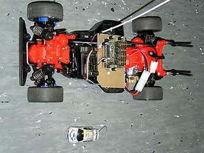
REMOTE CONTROLLED TOY CAR
Technical data of the controller
* Control Unit – the heart of a PIC16F628 by the company Microchip
* N-channel FET amplifier – bridge circuit with Motorumpolung and / or brake
* Input Voltage – 6 to 10 cells or 7.2 V to 18V
* Second peak electricity: 100A (depending on the type FET)
* Current: 60A (depending on the type FET)
* Internal resistance: 0.004 ohms constructed
* 1.5 A (only briefly, because no cooling)
* Under voltage detection
* Easy leveling with the remote control
* The tax needs to stick to neutral stand
* Monitoring of the recipient signal
* Current limit independent pre-trip ticket – Adjustable 5A in stages from 5A to 75A or without limit
* Adjustable parameters (now optimized for car models):
* Clock frequency – Switchable between 1900 Hz to 3900 Hz
* Delay Current limit for the start with an adjustable acceleration lag (slow start) adjustable delay
* Delay Current limit for driving with an adjustable delay acceleration of an adjustable delay
* Driving Mode – Forward – prev
* Driving Mode – Forward – brake
* Driving Mode – Forward – only then brake on billets center position to ride backwards
* Strength of the brake in the middle of billets
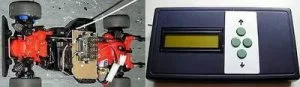
Technical data of the configuration unit
* Input via four buttons
* Operation of a LCD display (two lines with 16 characters)
* Downloading the rule parameters for control of an infrared interface (wireless)
* Permanent saving the last regulator to download data
* Permanent storage of different control configurations (not yet implemented)
* Power supply via a 9V battery
* A configuration management unit ID – only its own control to respond to this ID. Tourism controller can be no coincidence reconfigured. C compiler of CCS
Remote Controlled Toy Car schematic ccs c source code files alternative link:
FILE DOWNLOAD LINK LIST (in TXT format): LINKS-2440.zip
Source: REMOTE CONTROLLED TOY CAR PROJECT PIC16F877 PIC16F628
- What microcontrollers are used in this project?
The project uses the PIC16F877 and PIC16F628 microcontrollers from Microchip. - How is the motor drive circuit constructed?
It uses N-channel FETs in a bridge circuit capable of handling 60A continuous current and up to 100A peak. - Can the current limit be adjusted?
Yes, the current limit is adjustable in stages from 5A to 75A or can be set without a limit. - What input voltage range does the controller support?
The input voltage range is 6 to 10 cells, equivalent to 7.2V to 18V. - How are parameters configured and saved?
Parameters are configured via four buttons and an LCD display, then downloaded wirelessly via an infrared interface and permanently saved. - Does the system have under-voltage protection?
Yes, the controller includes under-voltage detection functionality. - What software is recommended for this project?
The article recommends using CCS C compiler software for programming the microcontrollers. - How does the braking system work?
The driving mode allows for forward, brake, or a combination where braking occurs when the control stick is centered.