Summary of Real time clock with 2 alarms and temperature sensing using PIC18F4550 and DS3231
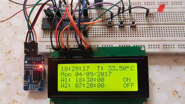
This article details an enhanced project interfacing a PIC18F4550 microcontroller with a DS3231 RTC to add alarm functionality and temperature monitoring. The system utilizes I2C communication, displaying real-time data on a 20x4 LCD. Users can set time, date, and alarms via three push buttons, while an LED indicates triggered alarms. The DS3231's built-in temperature sensor provides readings within ±3°C accuracy.
Parts used in the PIC18F4550 and DS3231 Alarm Project:
- PIC18F4550 microcontroller
- 20x4 LCD screen
- 10K ohm variable resistor
- 330 ohm resistor
- LED
- 3 x push button
- 5V supply source
- Breadboard
- Jumper wires
- DS3231 board (including DS3231 RTC chip, 3 x 4.7K ohm resistors, 0.1uF ceramic capacitor, 3V coin cell battery)
After the simple interfacing of the PIC18F4550 microcontroller with the DS3231 RTC, now let’s add the alarms functionality and temperature monitor to our previous project.
Interfacing PIC18F4550 with DS3231 project link:
Real time clock & calendar with PIC18F4550 and DS3231
As written in the datasheet the DS3231 RTC has a built-in 2 alarm functions and a digital temperature sensor with an accuracy of ±3°C.
Hardware Required:
- PIC18F4550 microcontroller
- 20×4 LCD screen
- 10K ohm variable resistor
- 330 ohm resistor
- LED
- 3 x push button
- 5V supply source
- Breadboard
- Jumper wires
DS3231 board contains the following components:
- DS3231 RTC – datasheet
- 3 x 4.7K ohm resistors
- 0.1uF ceramic capacitor
- 3V coin cell battery
The circuit:
Project circuit diagram is shown below.
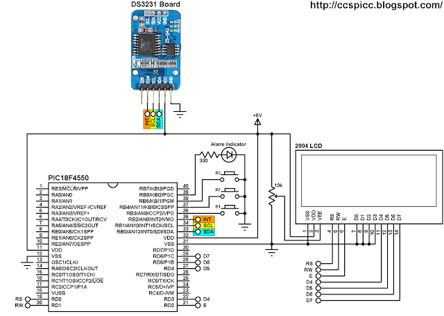
To simplify the circuit, I used the DS3231 board, this board basically contains the main chip which is the DS3231, pull-up resistors (4.7K) of SCL, SDA and INT/SQW lines and coin cell battery holder. There is also 24C32 EEPROM and some other resistors (not used in this project).
The DS3231 board is supplied with 5V as the microcontroller and the 2004 LCD, there are 3 data lined connected between this board and the PIC18F4550 MCU, SCL line is connected to pin RB1, SDA is connected to pin RB0 and INT line is connected to pin RB2 which is the external interrupt 2 pin of the PIC18F4550 MCU. The DS3231 interrupts the microcontroller when there is an alarm.
In the circuit there are 3 push buttons: B1, B2 and B3. These buttons are used to set time, calendar and alarms. Time and calendar can be adjusted with B1 and B2, button B1 selects time or date parameter (time parameters: hours and minutes; calendar parameters: day, date, month and year) and B2 increments the selected parameter. The button B3 and B2 adjust alarm1 and alarm2 parameters (hours, minutes and ON/OFF), button B3 selects the parameter and B2 increments the selected parameter.
There is an LED connected to pin RB6, this LED is used as an alarm indicator (alarm1 or alarm2), so if there is an alarm the DS3231 pulls down the INT pin which interrupts the microcontroller and the microcontroller turns the LED ON, here button B2 turns both the LED and the occurred alarm OFF.
In this project the PIC18F4550 MCU uses its internal oscillator and MCLR pin function is disabled.
CCS C code:
The C code below was tested with CCS C compiler version 5.051.
By reading the datasheet of the DS3231 RTC the code will be more easier!
The hardware I2C module of the MCU is initialized and configured using the following CCS C function with a speed of 100KHz:
#use I2C(master, I2C1, FAST = 100000)
I2C1: use first I2C module.
The DS3231 works with BCD format only (except temperature) and to convert the BCD to decimal and vise versa I used the following functions (example for minute variable):
minute = (minute >> 4) * 10 + (minute & 0x0F); // Convert BCD to decimal
minute = ((minute / 10) << 4) + (minute % 10); // Convert decimal to BCD
Code functions:
void DS3231_read() : this function reads time and calendar data from the DS3231 (seconds, minutes, hours, day, date, month and year).
void DS3231_display() : displays time and calendar data, before displaying time and calendar data are converted from BCD format to decimal format. This function displays the calendar by calling a function named void calendar_display() .
void alarms_read_display() : basically this functions reads alarm1 and alarm2 minutes and hours. It also reads the DS3231 control register, status register and 2 temperature registers.
The other job of this function is to display alarms data (hours, minutes and status) and the temperature value. The alarm status are extracted from the control register.
int8 edit(parameter, x, y) : I used this function to edit time, calendar and alarm parameters except the day. I used a variable named i to distinguish between the parameters:
i = 0, 1 : time hours and minutes respectively
i = 2, 3, 4: date month, year respectively
i = 5, 6: alarms hours and minutes respectively
i = 7: alarms status (ON or OFF)
After the edit of time/calendar/alarms the data have to be converted back to BCD format and written to the DS3231.
for more detail: Real time clock with 2 alarms and temperature sensing using PIC18F4550 and DS3231
- What features does the DS3231 RTC provide in this project?
The DS3231 RTC provides two built-in alarm functions and a digital temperature sensor with an accuracy of ±3°C. - How are the I2C lines connected between the DS3231 board and the PIC18F4550?
SCL is connected to pin RB1, SDA is connected to pin RB0, and the INT line is connected to pin RB2. - Which button is used to increment selected parameters for time and calendar?
Button B2 increments the selected parameter after B1 selects it. - How does the system indicate that an alarm has occurred?
The DS3231 pulls down the INT pin to interrupt the microcontroller, which turns on an LED connected to pin RB6. - Can the DS3231 operate in decimal format directly?
No, the DS3231 works with BCD format only, except for the temperature data. - What happens when the user presses button B2 during an alarm state?
Pressing button B2 turns both the alarm indicator LED and the occurred alarm OFF. - At what speed is the I2C module configured in the CCS C code?
The hardware I2C module is initialized and configured at a speed of 100KHz. - Which internal oscillator setting is used by the PIC18F4550 in this project?
The PIC18F4550 MCU uses its internal oscillator, and the MCLR pin function is disabled.