Summary of RC Servo Driver 0-5V
This article describes a 0–5V Servo Controller kit designed for hobbyist animatronics and motion control. The microcontroller-based board accepts a 5–6 VDC power supply and offers two control methods: an external variable DC signal or an onboard preset potentiometer. It features reverse polarity protection, a power-on LED, and clearly marked connectors for servo connection and signal selection via a jumper switch.
Parts used in the 0 – 5V Servo Controller:
- Microcontroller
- Berg connector (CN1)
- Jumper link (J1)
- Preset potentiometer (PR1)
- Power-on LED indicator (D1)
- Diode for reverse polarity protection (D2)
- Servo motor connector (CN2)
- PCB with mounting holes
0 – 5V Servo Controller project will control a hobby type servo motor connected to it via a preset or external DC source. This kit will be ideal add on in animatronics and motion control application.
Specifications
- Microcontroller based design for greater flexibility and ease of control
- Single Servo control via clearly marked berg connector
- Clearly marked jumper to select signal source to control the Servo
- Onboard preset for ready to control option for this kit
- Power-on LED indicator
- Diode protection for reverse polarity connection of DC supply to the PCB
- Four mounting holes 3.2 mm each
- PCB dimensions 45 mm x 32 mm
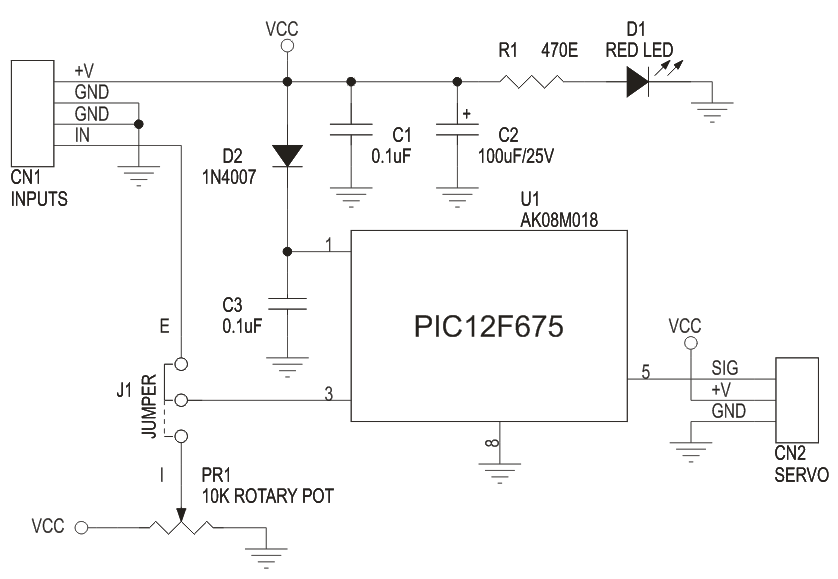
This is a simple but a useful circuit to control a single servo motor. Its an ideal add on to a RC Hobbyist tool kit. The DC input to this circuit should be 5 to 6 VDC. DC signal is given to this board at connector marked CN1 (+V and GND). You can also feed in a variable DC signal source at the other two pins on this connector to control the servo. To use this signal source you need to place the Jumper link at J1 in the E position. Alternatively, you can also control the servo motor by preset PR1 mounted on the PCB. For this you need to place the Jumper link in the I position at J1.A Servo motor is connected at connector marked CN2 on the PCB. This connector has all the pins clearly marked for connection to the servo.LED D1 is a power on indicator , Diode D2 provides a reverse polarity protection for the Microcontroller.
Schematic
For more detail: RC Servo Driver 0-5V
- What is the ideal application for this kit?
This kit is ideal as an add-on for animatronics and motion control applications. - Can you control the servo using an external source?
Yes, you can feed a variable DC signal source at CN1 by placing the Jumper link at J1 in the E position. - How do you control the servo using the onboard preset?
You must place the Jumper link in the I position at J1 to use the preset PR1 mounted on the PCB. - What voltage should be used for the DC input?
The DC input to this circuit should be between 5 to 6 VDC. - Does the board have protection against reverse polarity?
Yes, Diode D2 provides reverse polarity protection for the Microcontroller. - Where is the servo motor connected?
The servo motor is connected at connector CN2, which has all pins clearly marked. - What is the function of LED D1?
LED D1 serves as a power-on indicator. - Are there mounting options for this PCB?
Yes, the PCB includes four mounting holes, each 3.2 mm in size.