Summary of PWM MOTOR AND POWER CONTROL WITH PIC16F84
This article describes a PIC16F84-based PWM motor control circuit using a 4 MHz crystal to generate 100 Hz output with adjustable pulse widths. The system uses two buttons to increase or decrease power levels, suitable for specific engine applications. It includes schematic details for Proteus simulation and notes on oscillator components like capacitors and resistors.
Parts used in the PWM Motor and Power Control with PIC16F84:
- PIC16F84 microcontroller
- 4 MHz crystal oscillator
- Two push buttons (for power adjustment)
- Op-amp (for amplitude adjustment)
- 27pF health capacitors
- 130 ohm resistor
- Filtering components
- Display unit
- Reset button
- Inverter driven circuit
PIC16F84 4 MHz crystal is connected 100 Hz PWM output produces a pulse width of 10 separate levels are adjusted these values asm software vary from circuit only engine that not all GUS control applications can be used on… Electronics Projects, PWM Motor and Power Control with PIC16F84 “microchip projects, microcontroller projects, motor control circuit, motor driver circuit, pic assembly example, pic16f84 projects, pwm circuits,
PIC16F84 4 MHz crystal is connected 100 Hz PWM output produces a pulse width of 10 separate levels are adjusted these values asm software vary from circuit only engine that not all GUS control applications can be used on a frequency of 50 Hz is set inverters driven circuit two buttons have their power levels increase or reduce the works.
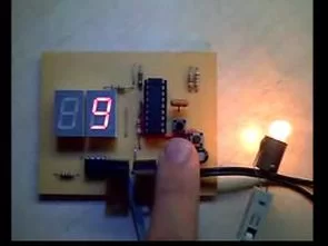
PIC16F84 PWM TEST
Level used appears from the display reset button resets the PWM frequency in LA PIC16F84 4MHz crystal oscillator if you use a frequency that can be altered according to the interests 100Hz 2MHz to 8MHz is used if you use 50hz 200hz Remove interests.
PWM output amplitude opamp using arttırabilin the filitrelenmesinde benefit var.devr schema Proteus plotted in I therefore some materials did not use crystalline to pins 27pF health capacitor and disciplinary pinlerine in series 130 ohm resistor bağlayınız.p connection from the top side, b, c, d, e, f, g, respectively, is going.
PWM Motor and Power Control with PIC16F84 pic asm code schematic :
FILE DOWNLOAD LINK LIST (in TXT format): LINKS-633.zip
Source: PWM MOTOR AND POWER CONTROL WITH PIC16F84
- What frequency does the 4 MHz crystal produce?
The 4 MHz crystal produces a 100 Hz PWM output. - How many separate levels are adjusted by the software?
The software adjusts ten separate levels of pulse width. - Can this circuit be used for all GUS control applications?
No, not all GUS control applications can be used on this circuit as it is designed for specific engine control. - What components are connected to the crystal pins?
Two 27pF capacitors and a 130 ohm resistor in series are connected to the crystal pins. - How is the power level increased or reduced?
Two buttons are used to increase or reduce the power levels. - Does the reset button affect the PWM frequency?
Yes, the reset button resets the PWM frequency display. - What range of frequencies can be altered if the crystal is changed?
If a different crystal between 2MHz and 8MHz is used, frequencies such as 50Hz or 200Hz can be set. - Is an op-amp used in the circuit?
Yes, an op-amp is used to increase the PWM output amplitude.