The present project called PLC with Pic CI16F877A is based on the operation of a PLC, today we can see these systems in industries, mining, etc. It is used to program an industrial PLC, it is the ladder language or (LADDER).
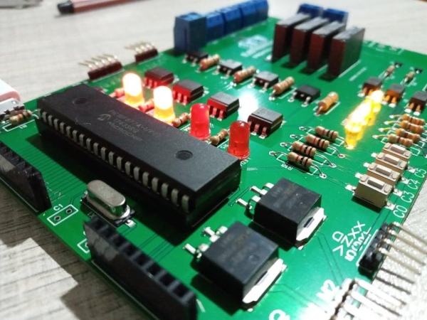
The project has the advantage of loading the program directly through the pickit3 so there will be no need to remove the microcontroller to program it.
PROJECT FEATURES:
Vin = 5v -12v
Vout = 3.3v – 5v
Relay outputs = 4
Outputs with Triac = 4
PWM outputs = 2
Direct programming with the PICKIT3
Button NO = 4
INPUTS = PORTA, PORTD
OUTPUTS = PORTB
MAX CURRENT = 1A
Bluetooth communication
Step 1: PIC16F877A – CARACTERISTICAS-DATASHEET
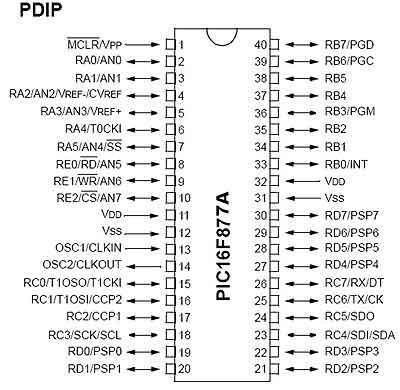
Powerful 40-pin PIC microcontroller, 33 of which are Input / Output. Ideal for the development of applications of medium complexity. It incorporates most of the peripherals needed in project development and offers considerable Flash memory space to store the program.
DATA SHEET: DATA SHEET PIC16F877A
DOWNLOAD DATSHEET MEGA: https://mega.nz/file/mMoCULIL#0qf5OJ2LeJkaCqliScbnsNKsKZt2o9qxM4W4QtLasvM
FEATURES
CPU = RISC type of 35 instructions
Data bus = 8 bits
Instruction bus = 14 bits
Program memory = 8 kB Flash type
RAM data memory = 368 bites
EEPROM / FLASH data memory = 256 bites
Maximum clock frequency = 20 MHz
Entry / Exit Lines = 33
Registers of special functions = 55
Addressing types = 3 (Direct, indirect and relative)
Flash Erase / Write Cycles = 100,000
Supply voltage range = From 2.0V to 5.5V
ICSP Circuit Serial Programming = Yes
Analog / Digital Converter = 1 of 10 bits – 8 Channels
Comparators = 2
SSP module = Yes
USART module = Yes
8 bit timer = 2
MSSP module = Yes
16 bit timer = 1
PSP module = Yes
CCP Module (PWM) 2
Step 2: SOFWARE PROGRAMACION (LADDER)
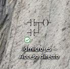
In this project we will see the programming software in LADDER or ladder language, it is LDMICRO, it is a very good software in ladder language programming and we can program any PIC, including ARDUINO of the ATMEGA family.
LDMICRO DOWNLOAD:
https://mega.nz/file/yEoEHRTb#8McMXsWlSJ_RXvmY2Wx3Kg5uW8TPRr7sAfLAqJawPTI
Step 3: Microcontroller Programming
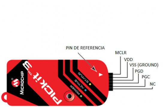
the programming or loading of the program that we carry out in LDMICRO and pass it to our PCB we will do it through the pickit3 directly since our PCB has the communication pins for loading the program and it is an advantage since we will not have to remove the chip to program it externally.
Step 4: How to Program LADDER Language in LDMICRO?
The programming in the LDMICRO software is identical to any of the programming software of other PLCs, in this case we already have 1 programs and it is the following:
- DIRECT START
These programs are well known and we tested our PROFESSIONAL PCB
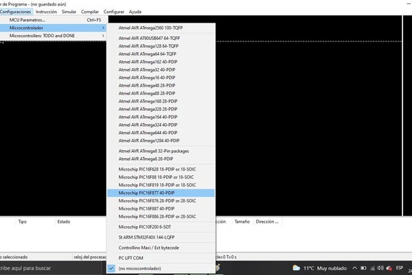
Next we will explain each of these programs but first we have to configure our chip to work and also our clock in MCU parameters, that is, for my case I am working with a 4MHZ crystal so my clock will be 4MHZ and my microcontroller the PIC16f877A once done this we will pass to the programming
Step 5: Direct Start
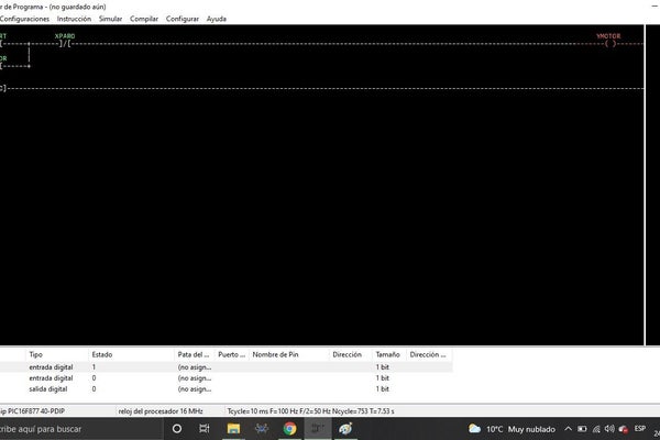
This program is well known and easy to carry out in the image we will see the START and STOP pushbutton we will see when we press START the motor will turn on and it will lock and start until we deactivate through the STOP pushbutton and if we want to stop the motor press the STOP button and the motor will stop until a new START pulse.
Once it is simulated and working, we go to the bottom part of the program where the contacts and outputs are that we insert and establish those inputs and outputs of our chip as we can see in the image.
Step 6: GENERAR ARCHIVO HEX
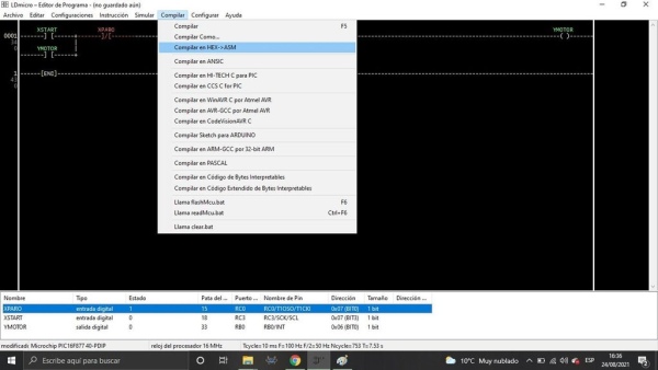
In this step we will see how to compile and generate different program files. In this case, for our PIC we will generate a hex file for loading to our PCB.
Step 7: Pickit3
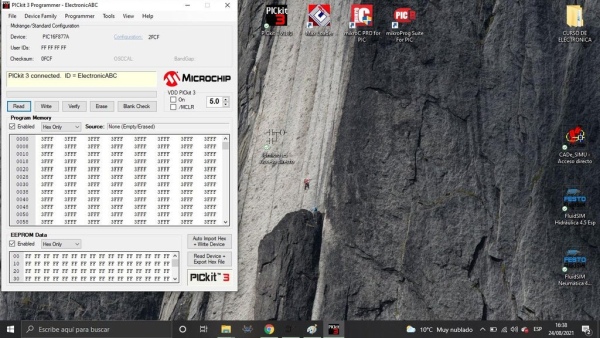
and finally we will enter pickit3 to load our program to the PCB directly with the pins that our PCB already has included and we see that it has already recognized it and we only load our HEX file already generated by the LDMICRO program AND we can AUTOIMPORT and ready our program will be in our PCB and we can do the test.
DIRECT BOOT HEX file:
https://mega.nz/file/2BAziQZQ#BgihXNWRC9-e8_lXTxqnm82PMQ5NPnb_Ns1oO9RNFck
Step 8: PCB SCHEME DIAGRAM
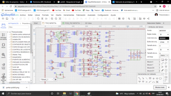
Here is the schematic diagram developed in the easyEdA software. It is a very professional program.
Here we can see what components we have used for the project.
Step 9: PCB – EASYEDA- JLCPCB
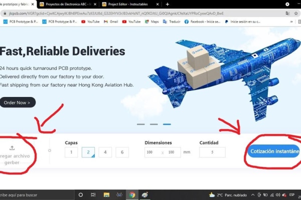
We thank our friends at JLCPCB for the professional boards to develop this project V1
you can order your pcbs at only 5PCBS at $ 2
my this link: https://jlcpcb.com/RAV
GERBER’S PROJECT HERE:
https: //mega.nz/file/PIZBUarZ#4_AFiJMnzgv279ceEIqB …
you can follow me on all my networks like ElectronicaABC
tiktok-facebook-youtube
Source: PLC Con El CI16F877A