Summary of Pimp My Rocket (Espresso Machine)
This article details a DIY project integrating an RGB LED strip with a Rocket Espresso machine to provide visual temperature feedback. Using a PICAXE 20M2 microcontroller, the system reads water temperature via a thermistor and adjusts LED colors through PWM. The author explains the circuit design, component selection, and programming logic to create a functional and aesthetic addition for espresso enthusiasts.
Parts used in the Coffee Machine Temperature Indicator:
- PICAXE 20M2 microcontroller
- Six RGB LEDs on adhesive-backed flexible strip
- 12V DC plug-in power adaptor (500 mA)
- 7805 voltage regulator
- BC337 transistors
- 10KOhm NTC thermistor
- 2.4K resistor
- 3.5mm stereo phono jack
- Prototype board and screw terminals
Combining Coffee and Electronics – An Idea for a Project
Having played around with fixed function logic ICs, such as the Johnson counter used in the Spindicator project, I was keen to move on and experiment with programmable microcontrollers. I decided to obtain and play with some PICAXE chips, as they looked like they would provide an easy introduction to using microcontrollers. Soon enough I was flashing LEDs and building touch-activated computer power switches. But what I really wanted to try was using the chip to control the colour of an RGB LED. For a suitable project I came up with the idea of using a strip of RGB LEDs to provide accent lighting for my Rocket Espresso coffee machine, where the colour of the LED would depend on the temperature of the machine (specifically the inlet water to the brew head). I thought this had the potential to not only look pretty, but actually provide useful visual feedback on the all important brew water temperature. If you are reading this because you’re a coffee geek interested in E61 HX type espresso machines, you may want to skip the electronics part and read the last section to see how it turned out.
PICAXE is a low-cost, easy to use microcontroller system which uses a simple BASIC like programming language. I’m not going to provide a tutorial on how to use and program PICAXE chips in this post. If you are interested in that, the PICAXE website has excellent documentation, free programming software, and lots of circuit and code examples. There are several different PICAXE chips you can buy, with different numbers of inputs/outputs and different inbuilt functionality. The inbuilt PICAXE function that is central to this project is PWM (pulse-width modulation).
 Controlling RGB LED Colour with PWM
An RGB LED is actually made of three LEDs under one lens, a red, blue and green LED (I’ll call these sub-LEDs). Each sub-LED can be switched on separately, so you can switch on blue and red to get purple for example. By switching each sub-LED completely on or off you can make six colours (red, blue, green, purple, cyan and yellow). In order to gain access to a complete spectrum of colours, you need to be able to precisely control the brightness of each sub-LED, and the way to easily do that is via pulse-width modulation. PWM controls the brightness of an LED by switching it on and off very fast (20,ooo times per second in my program), and controlling the amount of time it is on during each on-off cycle. The time for an on-off cycle is called the period (50µs in this case), and the time of the on pulse as a percentage of the period is called the duty cycle. So a for duty cycle of 50% at 20kHz, the LED will be switched on for 25µs, then off for 25µs. The switching is too fast for the eye to see, and so the overall result is that the LED will just look half as bright. Thus the LED brightness is directly proportional to the duty cycle. Most PICAXE microcontrollers have a PWM control function built in and accessible on one or more of the chip’s pins (see pinout diagrams in the PICAXE manual). Some PICAXE chips also have separate PWM control circuitry referred to as “HPWM”, or hardware PWM. The circuit and program described below uses the software PWM function. To control an RGB LED you need a chip with three (or more) independent PWM outputs such as the 14M2 or the 20M2. For this project I used the 20M2.
The Circuit
The circuit for this project is fairly simple as the PICAXE microcontroller does most of the work. For the LEDs I used a strip of six RGB LEDs. These are pre-wired to a strip of adhesive backed flexible circuit board as shown in the photo above. They come on a long roll which can be cut to any multiple of three LEDs. Initially I was going to use two sets of six, one mounted under the Rocket on each side. Consequently, this circuit is designed to drive 12 LEDs, and can drive up to 15 using the transistors and resistors specified. When I tried it though, I didn’t like the look of the reflections of the individual LEDs off the stainless steel bench on which my machine sits. In the end I decided to use one strip of six mounted behind the machine and reflecting a nice diffused colour off the wall behind. The first circuit diagram below shows the power supply for the PICAXE and LEDs. The 12 volt DC input is supplied from a small 500 mA 12V plug-in power adaptor. This 12V input is used directly as the power supply for the LEDs, and also as the input to a 7805 voltage regulator with 5V output. The 5V rail powers the PICAXE chip and peripheral circuitry. I added a small LED to the 5V output as visual confirmation of PICAXE power on. The switch on the 12V input is to assist with programming the PICAXE (the best way to program the chip is to initiate transfer from the computer with the power off, then quickly switch the power on). To save space I implemented this switch with a simple two pin header and jumper, which is actually a bit fiddly. If I were to build it again I would use a proper PCB-mounted mini toggle switch.
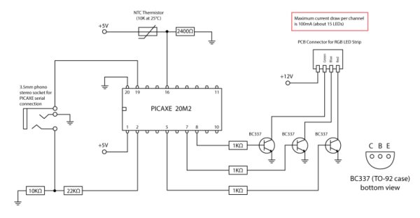
The rest of the circuit is shown in the diagram below. It can be divided into four parts; the 20M2 PICAXE chip itself, the serial programming interface circuit, the thermistor voltage divider and the LED switching transistors.
The serial interface part of the circuit consists of two resistors and a 3.5mm stereo phono jack, and is the standard minimum serial communication circuit as specified in the PICAXE literature. This can be used with either a simple serial cable (for connecting to a computer serial port, if your computer still has one), or the PICAXE USB cable. For a temperature sensor I used a standard 10KOhm NTC thermistor (a component whose resistance changes in response to temperature). The thermistor forms half of a voltage divider with a 2.4K resistor, the divided voltage being read by the PICAXE analog to digital conversion function (ADC). The value of 2.4K was chosen to give a reasonably linear relationship between the divider voltage and thermistor temperature over the range of interest (25 to 120°C), as well as the greatest change in voltage over this range. This relationship can be calculated, and is shown in the plot below for my thermistor, which has a specified calibration constant (beta) of 4,100K.
The PICAXE ADC function converts the voltage at the input pin to a number between 0 and 255 in direct proportion to the voltage. This number is then used by the program to calculate and adjust the duty cycle of each sub-LED (red, blue and green). Because the LED strip requires a supply voltage of 12V, and because a PICAXE output can only sink or source up to 20mA, the LEDs are switched via three BC337 transistors (for my final 6-LED configuration, I could have also used BC548 transistors with say a 2KOhm base resistor). For the particular RGB LED strip I used, I measured the 100% duty cycle current per sub-LED at 6.2mA (red), 5.5mA (green) and 5.7mA (blue). Thus for a strip of six LEDs, the maximum current that any transistor will switch is 37mA. In the circuit shown above, the BC337’s can switch 100mA and remain saturated (probably more, but that’s a safe figure), which means that the circuit will safely switch a strip of 15 LEDs (they come in multiples of 3 remember). By reducing the base resistor value you could switch a lot more LEDs, as BC337’s have a maximum collector current of 800mA (you may need a gruntier 12V supply than I’ve specified though, and don’t forget the PICAXE per-output 20mA maximum current, with 90mA maximum per chip).
 After going to some trouble to design a PCB layout in Illustrator, I decided that I couldn’t be bothered trying to etch a circuit board, so I made up the circuit using a prototype board and jumper wires, with screw terminals to connect the power supply, thermistor and LED strip. The board is illustrated below.
The rest of the circuit is shown in the diagram below. It can be divided into four parts; the 20M2 PICAXE chip itself, the serial programming interface circuit, the thermistor voltage divider and the LED switching transistors. The serial interface part of the circuit consists of two resistors and a 3.5mm stereo phono jack, and is the standard minimum serial communication circuit as specified in the PICAXE literature. This can be used with either a simple serial cable (for connecting to a computer serial port, if your computer still has one), or the PICAXE USB cable. For a temperature sensor I used a standard 10KOhm NTC thermistor (a component whose resistance changes in response to temperature). The thermistor forms half of a voltage divider with a 2.4K resistor, the divided voltage being read by the PICAXE analog to digital conversion function (ADC). The value of 2.4K was chosen to give a reasonably linear relationship between the divider voltage and thermistor temperature over the range of interest (25 to 120°C), as well as the greatest change in voltage over this range. This relationship can be calculated, and is shown in the plot below for my thermistor, which has a specified calibration constant (beta) of 4,100K.
For more detail: Pimp My Rocket (Espresso Machine)
- How does the project control RGB LED color?
The project uses pulse-width modulation to precisely control the brightness of each sub-LED, allowing access to a complete spectrum of colors based on temperature. - What microcontroller is used in this project?
The project utilizes the PICAXE 20M2 chip, which provides three independent PWM outputs required for controlling the RGB LED. - Can this circuit drive more than six LEDs?
Yes, the specified circuit can drive up to fifteen LEDs using the BC337 transistors and resistors provided. - Why was a 2.4K resistor chosen for the thermistor circuit?
A 2.4K resistor was selected to ensure a reasonably linear relationship between voltage and temperature over the range of 25 to 120°C. - What is the function of the 7805 voltage regulator?
The 7805 regulator converts the 12V input to a 5V rail that powers the PICAXE chip and peripheral circuitry. - How is the serial programming interface connected?
The interface consists of two resistors and a 3.5mm stereo phono jack, compatible with either a serial cable or a PICAXE USB cable. - Does the author recommend etching a PCB for this build?
No, the author decided against etching a circuit board and instead built the circuit using a prototype board and jumper wires.