I get wind of this Think Geek hacks contest, a week late, franticly, I hit thinkgeek.com looking for a easy kill, budget and ideas both turn up empty.
What about that pong kit I bought from them ~2 years ago? … hm when i first got it, I wanted it to be more game console like … what would be killer tho, I mean like super sweet … paddles!
Welcome to Pimp my Pong
Step 1: Start
The pong kit contains a write once pic microcontroller, its software and hard ware is set up to only accept digital input, that is to say it has a up and a down button for each player, along with a reset button … each button is either on or off depening if you want the paddle to go up or down.
After considering some “classic” based (potentiometer) controls, it soon proved to be a massive rats nest, and alot of resistors for only 8 notches between “full up” , and “full down” . What about a rotary encoder?
What is a rotary encoder?, your most familiar with it in your computer mouse, but those are optical, meaning they shine a lite past a shutter wheel to a “magic eye”, the one I will be using is of the magnetic type, which is most common on stereo equipment (ie a volume control in a car)
This type lets you have a compact knob, that can spin any either direction forever, and somehow knows which way its going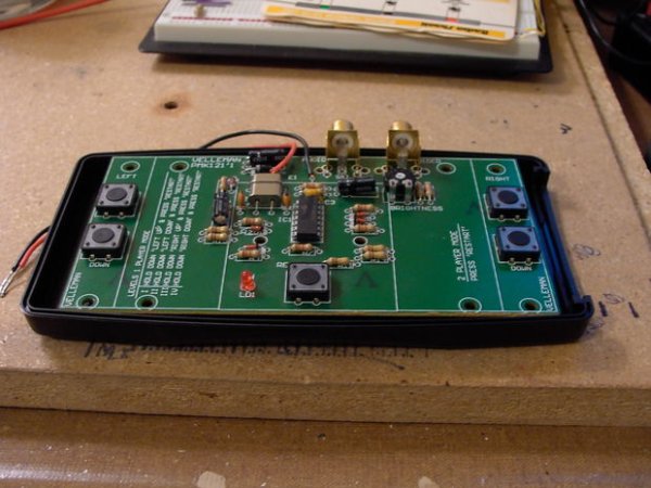
Step 2: Experimentation
I cant really explain the workings of a rotary encoder properly, but check
http://www.piclist.com/images/www/hobby_elec/e_ckt10_3.htm
for a full explanation,
Before finding the above site I was trying to make up my own circuit out of transistors and some basic understanding of transistor logic,
I had some success, and learned a lot more than I made progress. It almost kinda sorta maybe could have worked, but when I looked at it, I had made even more of a rats nest than the first idea, doesn’t matter anyway I cant get this in 2 days
Step 3: A deadline extinction
I check on the contest to see a 1 week extension. Its time to get cracking
I hit google, and found the before mentioned webpage
http://www.piclist.com/images/www/hobby_elec/e_ckt10_3.htm
And there, three sections down was exactly what I, and the pong game needed too! It was a 74xx logic chip, the 7474 d type dual flip flop
A rotary encoder hooked up to ~3 volts and some leds, while turned very slowly shows whats happening
each “bump” of the coder is divided into 4 sections, 1/4 of a “bump” in a given direction will turn on one of the 2 output pins, usually marked A or B
Half way through the bump the other pin will turn on
Three quarters, and the first pin turns off
100% and your off of the bump, the second pin turns off, and the encoder rest’s at off, which is like an open switch, nothing is passing
Depending on which pin turns on first dictates the direction, if A is on before B then its moving counter clockwise, if B is on before A its moving clockwise
there is a third pin, this is a common pin, it can be connected to ground, or (most commonly) +5V, the alps model I scavenged off of an old stereo handled +5V, so I have it hooked up to the +3V that the pong game requires
the 7474 acts as buffer, if A or B turn on first, the flip flop turns on one of 2 outputs (up or down) and ignores everything else until both A and B are turned off
Now there are different types of 7474’s out there, depending on how they are made, since pong only required 3v, and I had a 3v power supply, I wanted something that could run @ 3v
I went with a 74HC74, and got them from jameco
this series (HC) will run from 2 to 6 volts, which falls within pong’s specs
OK, to work we go!
Step 4: Parts & Tools
Single Controller (double parts for 2 controllers)
Rotary encoder, magnetic (allied electronics has some honeywells for ~5 bucks)
10K resistor *2
4.7K resistor *2
74HC74 D type flip flop
14 pin ic socket
6-7 foot phone cord, minimum 4 conductor, but 6 is fine
1N4148 diodes * 2
SPST momentary pushbutton switch
pactec PPL enclosure http://www.pactecenclosures.com/Plastic-Enclosures/PPL.html
4 conductor PCB mount RJ11 Female Jack
2×2 inch perfborad, and a ~1x 1.5 inch scrap piece (optional)
jumper wire
1.25 inch knob
double sided self stick foam pad
Console
1 Think Geek Classic Video Table Tennis Kit
http://www.thinkgeek.com/geektoys/science/8546/
1 pactec XPM enclosure http://www.pactecenclosures.com/Plastic-Enclosures/XPM.html
2, 2*2 inch perfboards
2 lengths of 2 conductor ribbon cable
1 length of 5 conductor ribbon cable
2 4 Conductor RJ11 female jacks
4 2222A NPN Transistors
1 Led
6 loose wires
1 wall wart, 3v (more like 4.2) 300ma, from a old style Game boy Advance (or better)
double sided self stick foam pad *2
Tools
Pliers
Tweezers
Wire cutters
Solder
Multimeter
Soldering iron
Damp yellow sponge
Lots of solder wick
Utility Knife
Xacto Knife
Xacto razor saw
Ruler
Band saw (optional)
Dremel (or in my case the crappy roto-matic)
Hand drill or drill press (i used a early 1970’s black and decker, its mean)
Jewelers file (optional)
Inkjet Printer (HP)
super glue
epoxy of your choice
double sided foam tape
screwdriver (Phillips and flat)
Step 5: Making room
I had the 74HC74’s mailed to my dads house, which gave me a opportunity to use his band saw
see, the full pong board almost fits into the enclosure, but I need to add power, and controller ports, and relocate the buttons, + wires + interface, I NEED more room
So after examining the underside of the board , most of the guts of the thing is in the center, the rest is just filler going out to the control buttons
I just used the bandsaw because it would be quick
Step 6: Salvage and scrap
If your pong is already assembled, nows the time to desolder the switches, be easy with them we need them for later
if you have the battery pack remove it, and replace its leads with a couple lengths of wire
Once I have saved what is needed, its to the band saw for some quick pcb reduction
Step 7: Add wires
Use your Xacto knife or jewelers file to lightly scrape the coating off of the paths we need
Solder a 2 conductor ribbon cable to the up and down paths for both players
Solder a single wire to the reset and led paths
and if you havent already replace the power wires
Tips:
leave your wires long, you can always trim them later, making them longer is trickier
soldering wire to a pcb without a hole is pretty easy, tin the newly cleaned off pad, tin the wire, then melt the 2 together
Step 8: Move Buttons
We still need a way to select the 4 different modes of single player mode (and they still control the game if desired) so we need to move the buttons to a floating board, so that they are all in one place and able to reach the top of the consoles enclosure.
I used a strip of 2×2 inch perf board, and it was a little short for all four buttons, but it ended up working. By the time I was at this stage, I could not find my saw and it was like 1am, so i really badly did the ole score and snap with a utility knife (and its nasty looking).
The switches that come with the pong kit have 4 pins, if you position the switch where the leads are pointing up and down the 2 on the left are connected, the 2 on the right are connected, and only when the button is pushed are all four connected, so its just a simple SPST momentary switch, same is true of most tactile switches like this.
Insert your switches into the perfboard .
We need to connect 1 side of every switch to ground. To do this I “stitched” and looped some copper wire to all the Odd numbered pins on the left hand side of the board. Then soldered all the pins on that side.
on the right hand side I connected the 5 conductor ribbion cable, 4 go to the even numbered pins, and number 5 goes to any odd pin to connect the other side
Step 9: Controller Interface and power distribution
The paddle controller I whipped up sends 3 volt pulses, pong sends 3 volts to a button, and its active when shorted out to ground, SO we need a way to use the paddle pulses to a switching action for pong
This is accomplished with 2 NPN transistors per player, when the center pin has voltage going to it, the 2 outer pins connect the correct pins on the pic chip to ground, and thus signaling a button push
We also need a way to attach a cord between the console and paddle, I settled on some 4 conductor RJ11 female telephone jacks
Since the controllers require 2 wires for up and down signal pulses, power and ground, the power distribution got shoved on this board too, along with the grounds of the reset switch and led
Along with everything else we need to connect the pong control wires we soldered to the chopped up main board AND the ribbon cable that goes to the 4 buttons
the final wiring of this ended up being quite complicated, and i will post a full schematic shortly
The first thing i did was pop the jacks in place, and did a test fit in the enclosure
Next I hooked up the wall wart to the edge of the board, leaving the stripped wire long so it could reach a bit and only soldered the 2 end points to form a bus, since there is going to be a LOT of stuff connected to ground
Then I probed the phone jacks with my multimeter and decided which pins would be ground, +V, up data, and down data, I ended up with U,V,D,G on mine. So I ran jumpers from the power supply to the appropriate pins on both phone jacks, plugged in the wart and probed again to make sure
Step 10: Transistors
Next I need to install a transistor for each direction on each player, again when the paddle sends its signal its a 3 volt pulse, the buttons on pong need to connect to ground in order to register a push. this conversion is done with NPN transistors (type 2222)
Naturally lets start with player 1 up
If you hold the transistor where the flat part is facing you the right pin needs to connect to ground, the center pin needs to connect to the P1 phone jack (wherever you decided to put your incoming up signal) and the left pin needs to connect to the pong board with the wire we soldered on earlier, ALSO we need to connect the button board’s ribbon cable so that the first button + wire goes tp the left pin of the transistor
Repeat 3 more times for P1 down and P2 up and down
While were at it, Im going to solder a pair of wires to power supply’s ground, then to both the LED and the reset switch, then solder the positive wires we already ran to both
And lastly connect the pong boards power leads to the wall wart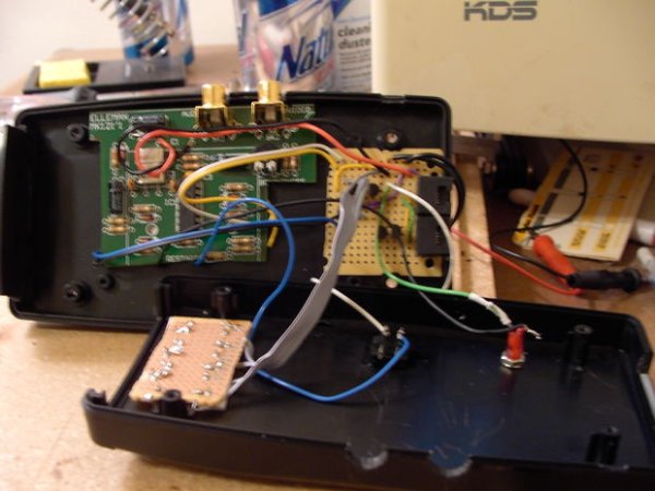
Step 11: Making the paddle controller
It would be wise to plug up and test the console now that we have all the wiring done, test each button and I used a bit of wire connected to the wall wart to test the up and down on the phone jacks, if everything works we can start making the paddle
NOTE: I only made one due to time and money
The website I had mentioned earlier (http://www.piclist.com/images/www/hobby_elec/e_ckt10_3.htm) gives a excellent description of whats really going on, but it only really shows the basics, there is abit more to the circuit than what is shown on that page
Also we need a way to push both directions at once to signal a ball launch
again construction is pretty standard, put your biggest stuff on first so you have room and hook it all up, the rotary encoder is connected via a 3 conductor ribbon cable and a strip of perfboard (to make it easier and, so we can later bolt it to the face of the enclosure) and the pushbutton fire switch is connected with a couple loose pieces
VERY IMPORTANT NOTE
I bought a 7 foot long 6 (we only need 4) conductor telephone cable at my local k-mart, and I soldered everything together, when I plugged up the circuit (without the 74HC74 plugged into the socket) and checked my voltages everything was backwards! Thats when I noticed the phone cable is wired backwards on one end
It was 1 am Saturday at that point, so I opted to just lop off the end of the phone cable and install a new male jack (cause I can), but if you dont / cant do that be sure to probe out your wire and make adjustments
in my case the console jacks were wired UVDG, so the paddle side really needed to be GDVU so the correct things ended up on the correct wires
For more detail: Pimp my Pong