Summary of I2C Communication using TMS320F28027PT with Proteus Simulation
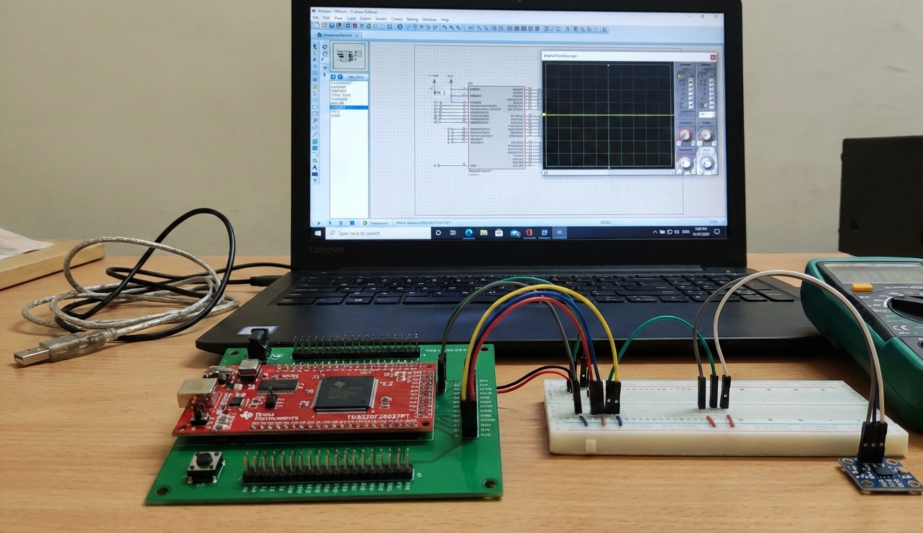
This project implements I2C master communication on a TMS320F28027PT Piccolo MCU within a Proteus simulation, demonstrating startup, watchdog-safe boot, precise assembly microsecond delays, and I2C signaling with pull-up resistors. DIP switches provide inputs and dual 7-segment displays show outputs, making timing, initialization, and bus behavior observable for learning and firmware debugging.
Parts used in the I2C Communication using TMS320F28027PT with Proteus Simulation:
- TMS320F28027PT Piccolo MCU
- I2C pull-up resistors
- DIP switch (8-position)
- Resistor pack (RESPACK-8)
- Dual 7-segment displays
- Power and ground connections
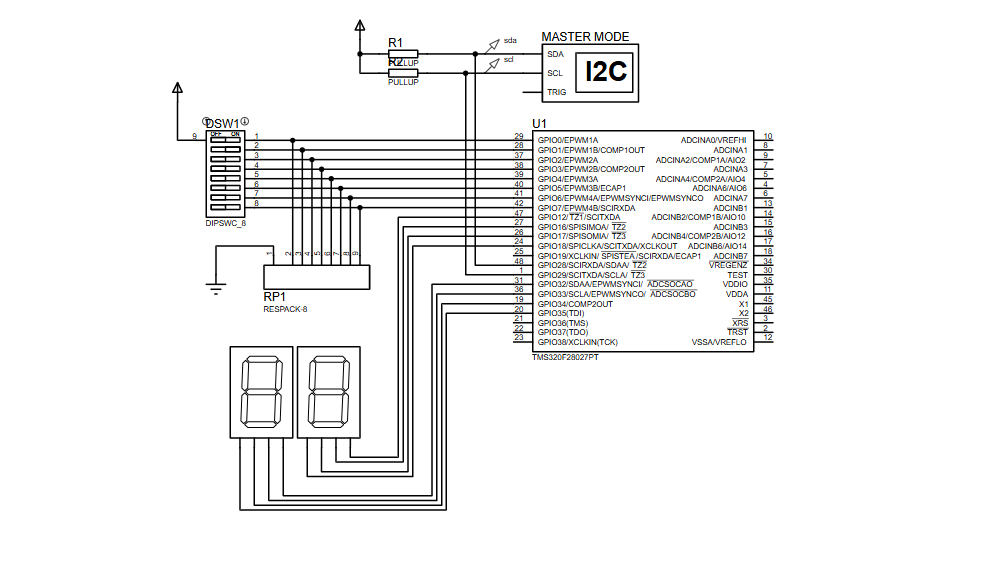
- Why are pull-up resistors required on SDA and SCL?
I2C uses open-drain signaling, so pull-ups maintain valid logic levels. - Why must the delay function run from zero wait-state RAM?
Wait states increase execution time, affecting delay accuracy; zero wait-state RAM preserves accurate microsecond delays. - Can this project work on real hardware?
Yes, the firmware is suitable for deployment on an actual TMS320F28027PT. - What happens if interrupts are enabled during delay calls?
The delay may become longer than expected. - Can this project be extended to EEPROM or sensors?
Yes, the I2C master setup supports such extensions. - Why is the watchdog disabled at startup?
To prevent unintended resets during initialization. - Is this compatible with other Piccolo devices?
Yes, with minor pin and clock adjustments. - What visual outputs are used to observe behavior in the simulation?
Dual 7-segment displays reflect output behavior during the Proteus simulation.